Editing
The Bot Editor is where you author a .superdex_bot. Opening a bot loads it
into a live simulation surrounded by dockable windows, so every edit is
immediately visible in motion. The default layout adds three windows around the
viewport: Bot Hierarchy, Bot Details, and Bot Link Details, each
covered in its own section below. In the figure, Bot Details and Bot Link Details
share a dockspace, but all tabs can be arranged however you like.
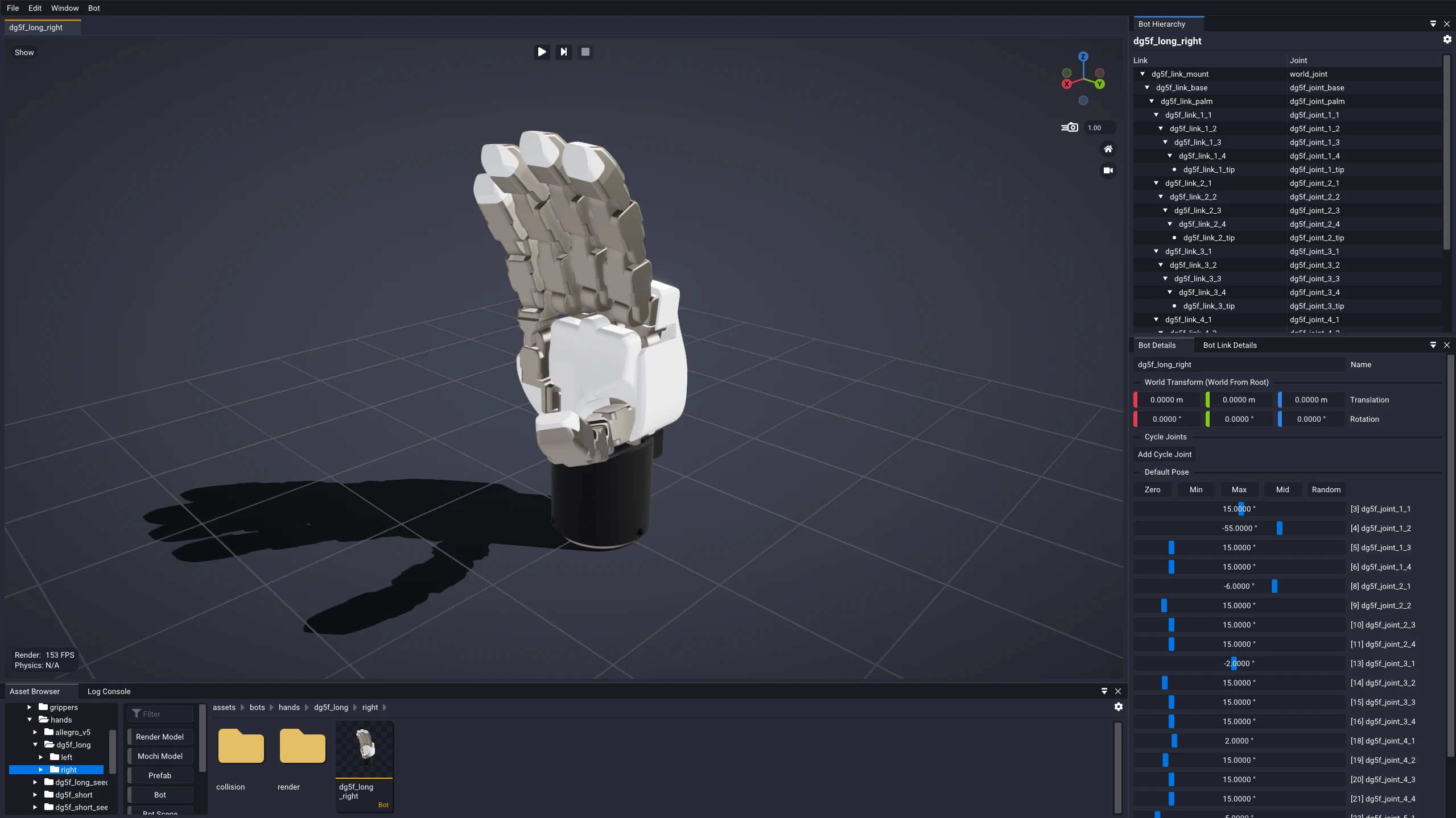
This layout is only a starting point. Drag the tabs to rearrange or re-dock the windows however you like, and your arrangement persists across sessions. Docking Bot Hierarchy and Bot Details side by side, for instance, is handy for bots with a large number of links. If you accidentally close a window, reopen it from the Window menu in the main menu bar.
Creating or Importing Bots
There are two ways to get a bot into the editor. To start one from scratch, right-click in the Asset Browser and choose Create > Bot..., which makes a new, empty bot and opens it in the Bot Editor.
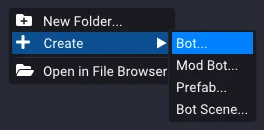
Building a bot from scratch is fully supported, but it suits only simple, one-off bots. Assembling a complex robot link by link is tedious and error-prone. For anything nontrivial, prefer importing the robot instead, from an existing URDF or a SuperDex CAD Exporter export, which brings in the full link hierarchy, geometry, and inertial properties in one step.
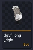
However a bot was made, open it for editing by double-clicking its asset tile in the Asset Browser.
Bot Hierarchy
The Bot Hierarchy shows the robot's kinematic hierarchy: the parent-child relationships between its links and joints. The tree has two columns, Link and Joint, and each row pairs a link with its inbound joint. Read a row as this link is attached by this joint, and the joint in turn hangs off the link of the parent row, the next row up the tree toward the root. Walking the rows this way traces the kinematic chain outward from the base to the tips.
The one exception is the very first row. Its joint is the World Joint, and rather than connecting two links it describes how the robot's root is anchored to the world: left Free to float and be pushed around, or made Hard to weld it rigidly in place.
The tree can be shown in two orderings, toggled from the settings cog. Show
Links in Hierarchical Order (the default) nests each link under its parent,
mirroring the kinematic chain. Show Links in Data Order instead lists the
links and joints flat, in the order they are stored in the .superdex_bot asset.
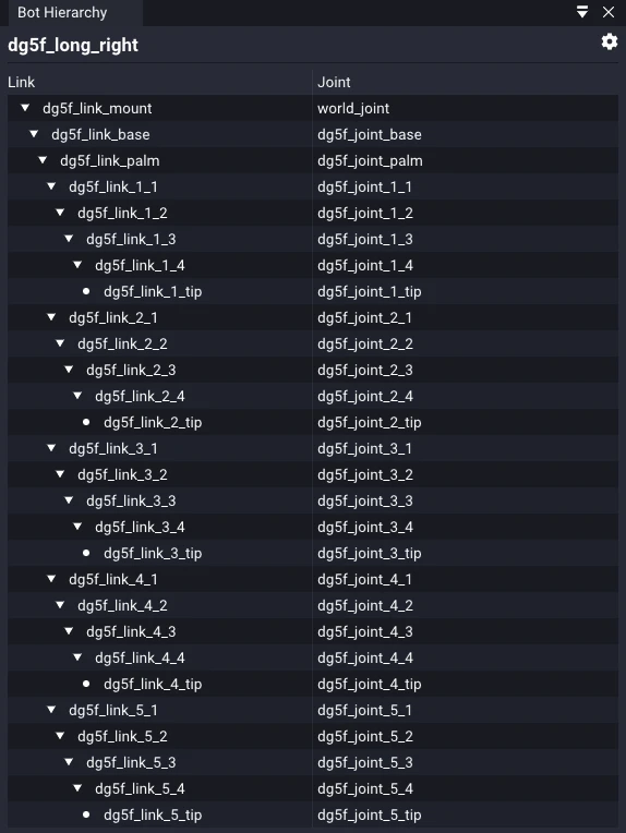
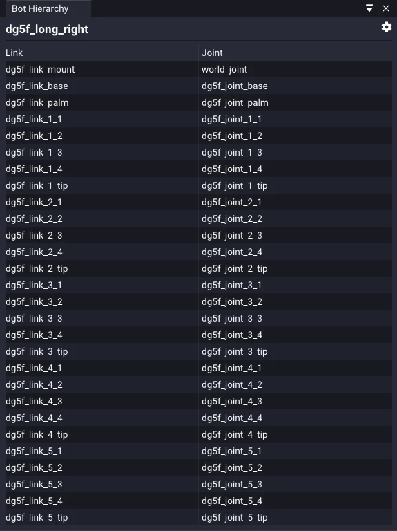
Clicking the robot's name at the top of the tree brings Bot Details forward. Clicking any link row below it selects that link: the link highlights orange in the viewport and its properties open in Bot Link Details below.
Right-click any link in the tree to edit the bot's structure directly:
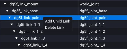
- Add Child Link appends a new, empty child link, with its own joint, beneath the link you clicked.
- Delete Link removes that link together with its entire subtree of descendants. It is disabled for the root link.
Use these to shape the robot's own permanent structure. When what you really want is modularity, such as attaching a hand to an arm or swapping one tool for another, don't bake the extra links into the base bot; compose them as Mod Bots instead.
Hovering a row highlights that link in blue in the viewport, so you can find which part of the robot a row refers to without selecting it.
The tree can't be rearranged by dragging rows. To change a link's parent, use the Parent dropdown in Bot Link Details instead.
Bot Details
Bot Details collects the bot's top-level properties, the ones that belong to the bot as a whole rather than to any particular link or joint.
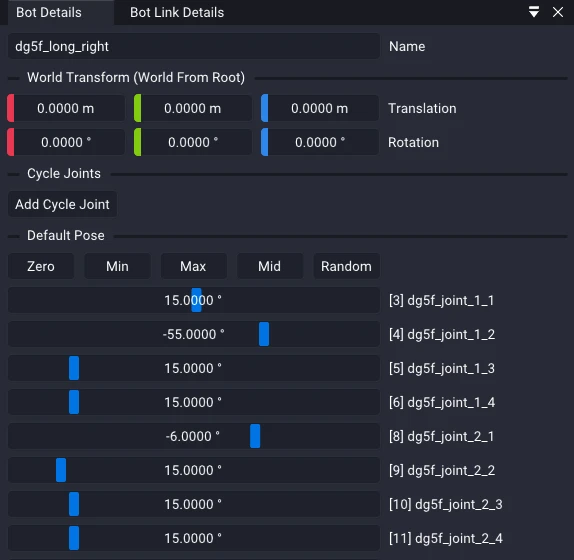
World Transform is the bot's spawn transform, where its root is placed in the
world when the bot is instantiated into a scene. It maps to the bot format's
worldFromRoot
field, a TransformRT from the root link to the world frame. It is typically left
at identity and set by whatever consumes the .superdex_bot at runtime; it is
exposed here mainly for debugging.
Default Pose sets the joint configuration the bot spawns in. Each actuated degree of freedom gets its own slider: revolute and prismatic joints are a single slider apiece, while a spherical joint expands into three, one per axis (X, Y, Z). The Zero, Min, Max, Mid, and Random buttons set every DOF at once.
Cycle Joints
Most robots are open kinematic trees, but some mechanisms, such as parallel grippers and four-bar linkages, close a loop that a tree cannot represent on its own. Cycle Joints add that missing connection back: each one is a soft spherical constraint that ties two links together to close the loop. The Robotiq gripper below is a classic case, its linkage forming a closed loop between the finger and its coupler.
New cycle joints are added by clicking Add Cycle Joint (available once the bot has at least two links). Each cycle then expands to reveal its fields, and the trash button beside it removes it.
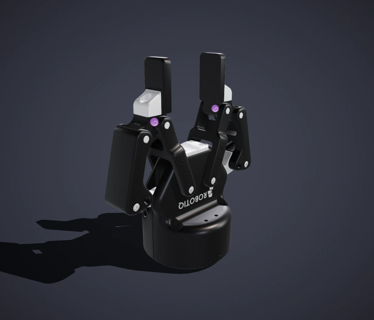
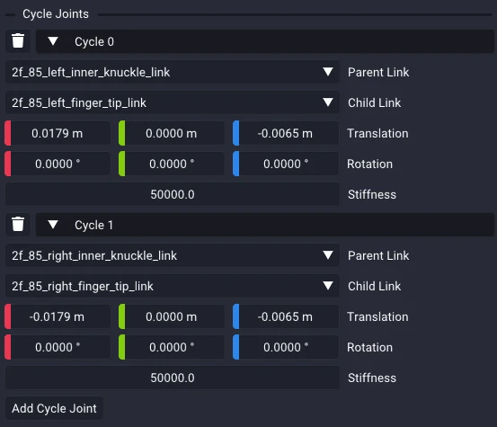
Each cycle joint maps directly to the bot format's
ArticulatedCycleJointParams
and exposes four fields:
- Parent Link and Child Link: the two links the constraint ties together,
chosen by name and stored as indices into the bot's links (
parentLink,childLink). Closing the loop between them is exactly what the tree hierarchy cannot express. - Joint From Child Link: the transform placing the constraint's joint frame
relative to the child link (
jointFromChildLink, aTransformRT). - Stiffness: how firmly the constraint holds the loop closed (
stiffness, default50000).
Bot Link Details
Bot Link Details shows the properties of the link currently selected in the Bot Hierarchy, together with the joint that connects it to its parent. At the top is a Parent selector, followed by two collapsing sections, Joint and Link.
Parent
The Parent dropdown reassigns the selected link to a new parent. It is how you reorganize a bot's kinematic structure directly in Studio, without going back to the source description and re-importing.
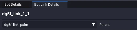
Reparenting moves the whole subtree: the link's children keep pointing at it, so they come along and the branch stays intact. Studio also preserves the link's world transform rather than its local one. It recomputes the joint's local placement (its Parent Link From Joint transform) from the bot's default pose so the link stays where it was in the world, with only its attachment point changing.
The selector appears only for a non-root link of an editable bot, and not while simulating. It also hides the link's own descendants, since parenting a link beneath itself would create a cycle.
Joint
The Joint section edits the joint that attaches the link to its parent (for the root link it is labeled World Joint). Rather than a flat list, its properties are organized into groups:
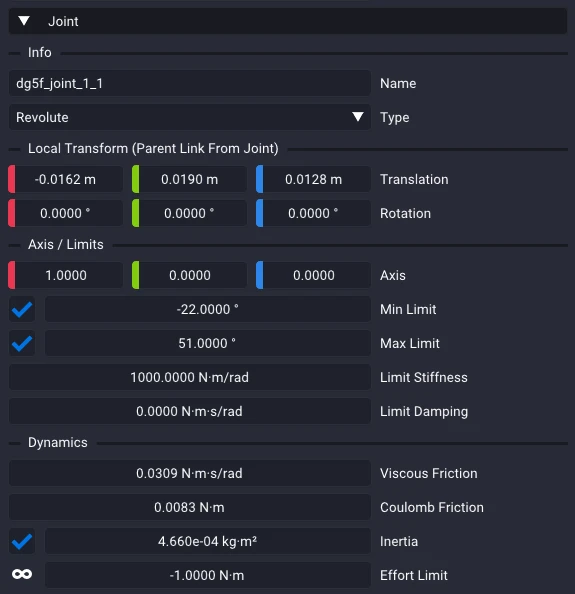
- Info: the joint's name and its type (Free, Revolute, Prismatic, Spherical, or Hard).
- Local Transform (Parent Link From Joint): where the joint frame sits relative to the parent link.
- Axis / Limits: the axis of motion, its lower and upper limits, and the stiffness and damping that resist them. Spherical joints expose per-axis (X, Y, Z) limits.
- Dynamics: the joint's friction (viscous and Coulomb), inertia, and effort limit.
Min Limit, Max Limit, and Inertia are optional; toggle the checkbox to
set one, and a limit left unset leaves the joint unbounded in that direction. The
Effort Limit instead encodes its regime in the value itself: a negative value
such as -1 means unbounded (no effort limit is applied), 0 means
non-actuated (no effort can be applied, though the joint still moves freely
within its range), and any positive value clamps applied effort to that magnitude.
For the exact fields within each group, along with their units and defaults, see
the robotics API's
BotJointPrefab.
Link
The Link section covers the link itself: its identity, placement, mass, and collision geometry.
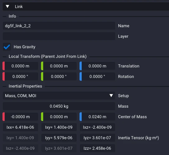
- Info: the link's Name, its collision Layer, and whether it Has Gravity.
- Local Transform (Parent Joint From Link): the link's translation and rotation relative to its parent joint.
- Inertial Properties: the link's mass distribution. A Setup mode chooses how it is specified (from density or explicit mass, with or without a center of mass and moment of inertia) and exposes Mass, Center of Mass, and the symmetric Inertia Tensor.
The Setup mode controls how much of the link's mass properties you enter by hand versus letting Studio compute them from the collision geometry:
- Default: mass, center of mass, and inertia are all computed from the shape, assuming a uniform default density.
- Density Only: the same, but you choose the material density.
- Mass Only: you set the total mass, and the center of mass and inertia are still taken from the shape and scaled to match.
- Mass, COM, MOI: you specify mass, center of mass, and the inertia tensor by hand.
- Density, COM, MOI: you set the density (mass follows from the shape) and provide the center of mass and inertia yourself.
Links without collision geometry, such as bare frames or tool tips, carry no mass properties at all.
Below Info are the link's two models: the Collision Model (the .mochi.h5
shape used for physics) and the Render Model (the .glb mesh used for
display).
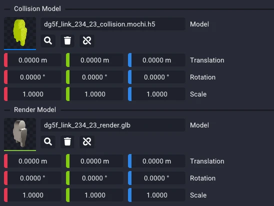
Populate or update either model by dragging the matching asset from the Asset Browser onto its tile, or double-click the tile to jump straight into the Model Editor for that link's model. The magnifying glass selects the current asset in the Asset Browser, and the trash button clears the slot.
Each model carries its own transform (translation, rotation, and scale) relative to the link frame, so the collision and render meshes can be offset independently when they are not colocated.
When the two models are colocated, toggle the Link button beside the trash icon to keep their transforms in sync, so an edit to one model's transform is mirrored onto the other.
New collision models can be created from CAD or visual assets right inside Studio. Changing the visual appearance of a render model, such as its shape, materials, or textures, is left to dedicated tools such as Blender or Substance and is out of scope for Studio. To restyle a bot, open its render model asset in one of those applications, make and save your edits there, then reload the bot in Studio to pick up the changes.
Finally, the Collision / Contact section gathers the advanced contact and collision properties that SuperDex Physics uses to resolve contact for this link. They are tuned for typical robots and can almost always be left at their defaults.
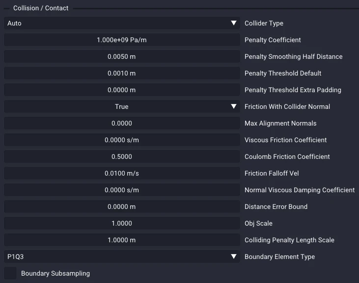
When you do need to adjust them, they fall into a few buckets:
- Collider Type chooses how other bodies detect contact with this link, its collision representation. Auto (the default) derives a suitable one from the shape, such as a signed-distance field for a mesh link, and is right for almost all bots.
- Penalty Coefficient, Penalty Smoothing Half Distance, and the Penalty Threshold fields tune how firmly the link resists penetration and the distance at which contact begins to engage. A higher penalty coefficient gives stiffer contact with less interpenetration.
- Coulomb Friction Coefficient, Viscous Friction Coefficient, and Friction Falloff Vel set how strongly the surface resists sliding and how that resistance ramps in at low sliding speeds, while Friction With Collider Normal selects which surface's normal defines the friction plane.
- Normal Viscous Damping Coefficient dissipates energy along the contact normal, controlling how much an impact bounces.
- Boundary Element Type and Boundary Subsampling determine how the contact surface is sampled for the solver, and are rarely changed.
For the full contact model and the precise meaning of each parameter, see the SuperDex Physics guide to Contact.
Bot Contact
The Bot Contact window is an advanced editor for a bot's per-link contact behavior. It is not part of the default layout; open it from the Window menu when you need it. It presents an upper-triangular matrix with one checkbox per pair of the bot's links: checked means the two links are allowed to collide, and unchecked disables contact between them. This is how you manage a robot's self-collisions, letting the links that are meant to touch interact while stopping neighboring or overlapping links from fighting each other.
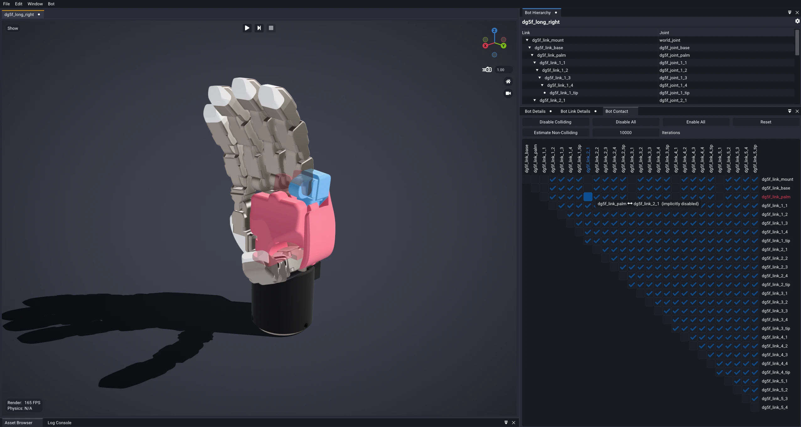
By default, SuperDex Physics disables contact between each link and its parent, its
nearest physics-bearing ancestor (see
BotContactOverride).
Those pairs show up as the unchecked, subdued cells. Every other pair is
enabled by default, shown as a checked, subdued cell.
Toggle any box to override its default. The cell becomes less transparent to mark it as an explicit override of your own.
Hovering a cell highlights the two links it refers to in the viewport: the column link in blue and the row link in red.
A row of buttons across the top of the window applies bulk actions:
- Disable Colliding poses the bot at its Default Pose, steps the simulation a single tick, and disables contact for every pair of links found actually touching in that pose. This is the quick way to clear links that start out interpenetrating at rest, which is common right after an import. Because it only inspects the default pose, it will not catch collisions that appear elsewhere in the bot's range of motion, so sanity-check the result.
- Disable All disables contact between every pair of links.
- Enable All enables contact between every pair, including the parent-child pairs that are disabled by default.
- Reset clears all of your overrides, returning every pair to its default (parent-child disabled, everything else enabled).
- Estimate Non-Colliding samples the bot in many random poses and disables any link pair that is never caught colliding across all of them. Turning off contact for pairs that can never touch is a worthwhile performance optimization. Set Iterations high enough that the result stops changing between runs, so it converges on a consistent set, and always sanity-check what it disables. The estimate is deliberately conservative: it drops the bot straight into arbitrary random poses, including many a real controller could never reach without first driving the bot through other links, and a single collision in one of those unreachable poses is enough to keep a pair enabled. In practice, it tends to leave more contacts on than are strictly necessary.
Other Editing Features
A couple of bulk tools live in the Bot menu on the main menu bar.
Batch Link/Joint Rename
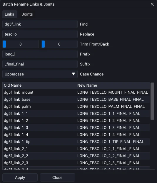
Bot > Batch Rename Links & Joints... renames many links or joints at once. Enter a Find and Replace string, trim characters from the front or back, add a Prefix or Suffix, and apply a Case Change; a live preview table shows each Old Name next to its resulting New Name before you commit. Links and joints are handled independently on their own Links and Joints tabs, so switch tabs to rename each set.
Bake Mass and Inertia
Bot > Bake Mass & Inertial Properties computes and bakes a mass, center of mass, and inertia tensor onto every link whose inertial properties are parameterized by density or mass only. The values are derived from the link's collision geometry under a uniform-density assumption.
This is not a substitute for proper system identification or CAD-derived mass and inertia, which are what you should use for real robot links. It is useful for rough estimates, simple examples, or a baseline to compare against.