Visualization
The Bot Editor offers a number of visualization and debug features that help you assess the overall quality and health of a robot. Some are shared with the other editors, and some are unique to the Bot Editor.
Toggle Visualizations
The Show menu, in the top-left corner of the viewport, toggles each visualization on and off. Every entry is a checkbox, and many also have a keyboard shortcut you can use without opening the menu.
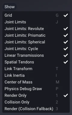
| Visualization | Shortcut | Description |
|---|---|---|
| Grid | G | The ground reference grid. |
| Joint Limits | J | Joint axes and range-of-motion indicators. |
| Link Transform | T | Each link's local coordinate frame. |
| Link Inertia | I | A box at each link approximating its inertia. |
| Center of Mass | M | A marker at each link's center of mass. |
| Physics Debug Draw | P | Debug overlays from the live SuperDex Physics simulation. |
| Render Only | 1 | Show only the render meshes. |
| Collision Only | 2 | Show only the collision meshes. |
| Render (Collision Fallback) | 3 | Show render meshes, falling back to the collision mesh for links that have none. |
The last three are mutually exclusive display modes that choose which geometry the viewport draws.
Joint Limits
Joint Limits overlays each joint with its axis and an indicator of how far it can travel. Revolute joints show an arc fan sweeping their angular range, spherical joints show three fans, one per rotation axis, and prismatic joints show their linear travel as a track marked at both ends. Cycle joints are drawn here too, each marked with a sphere at its pivot.
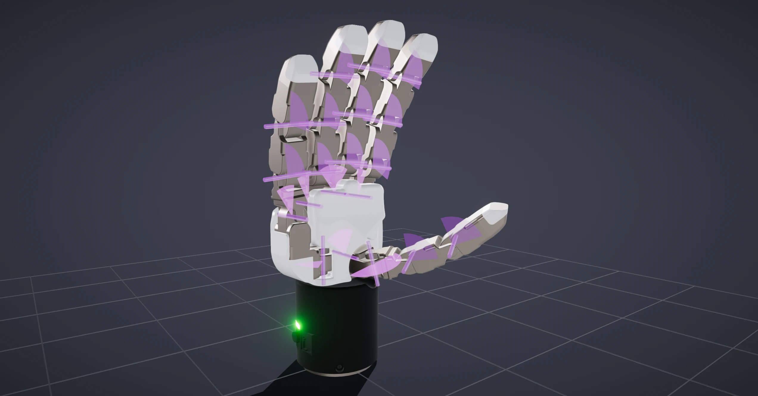
Use the Joint Limits: Revolute, Prismatic, Spherical, and Cycle entries in the Show menu to choose which joint types are drawn.
Link Transform
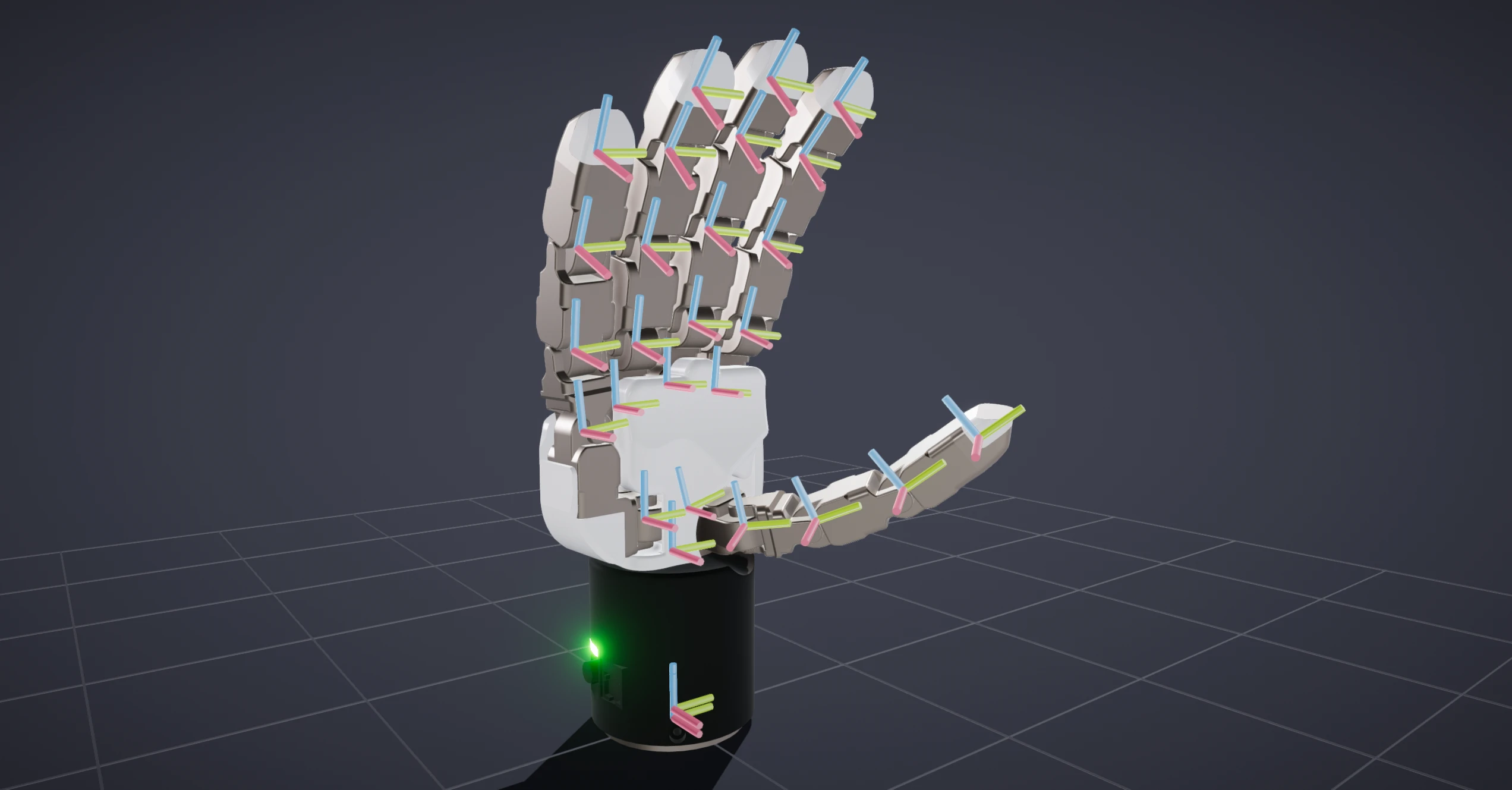
Link Transform draws each link's local coordinate frame as an axis triad, with X in red, Y in green, and Z in blue. It shows where each link's origin sits and how it is oriented, which makes it easy to confirm that imported frames line up the way you expect.
Link Inertia
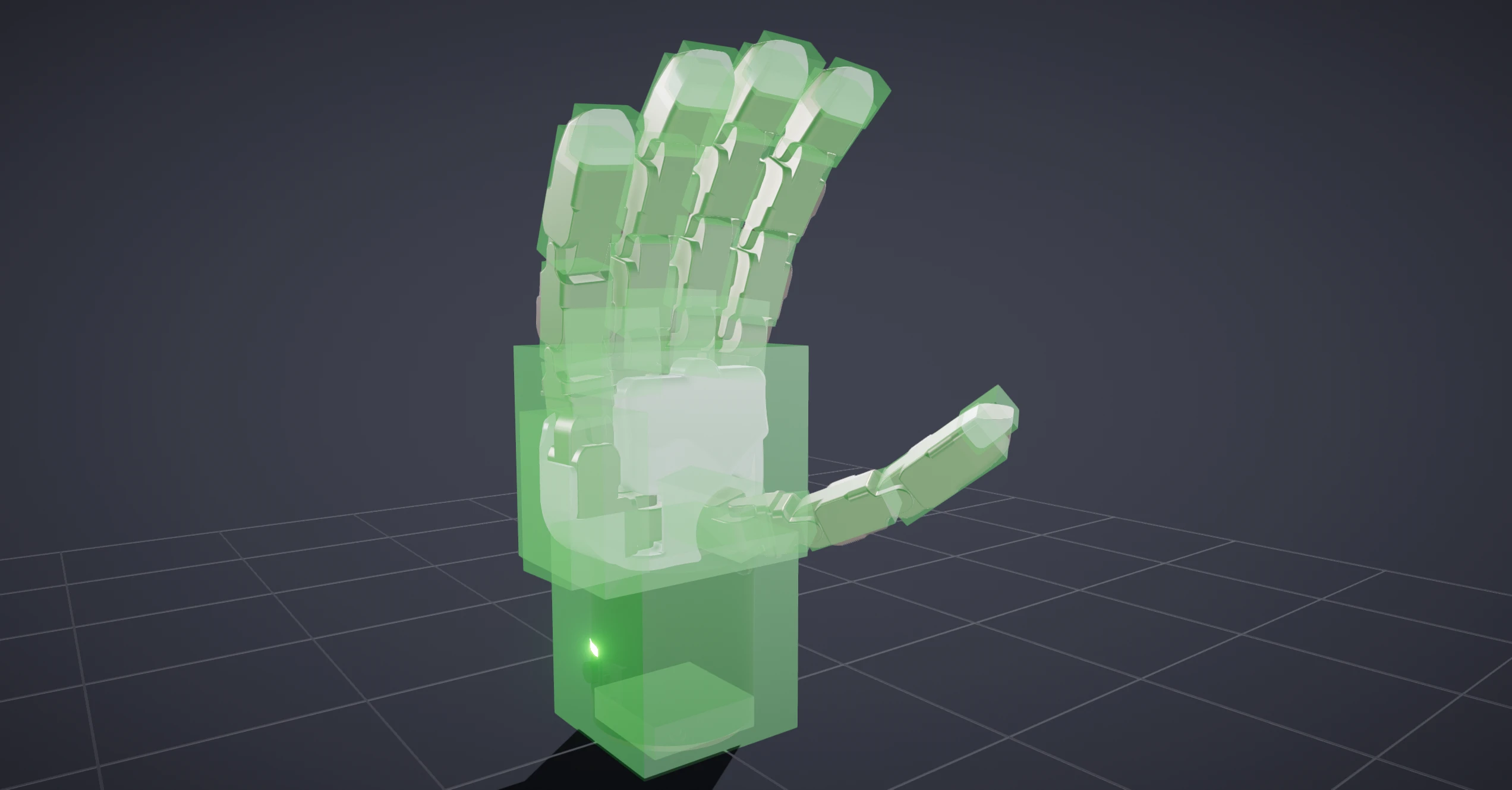
Link Inertia overlays each link with a translucent box that stands in for its rotational inertia. The box is the uniform-density box that would have the same mass and the same moment of inertia as the link, centered at the link's center of mass and aligned to its frame.
Read it as a picture of how the link's mass is spread out: a bigger box means more inertia for the same mass, and its proportions along each axis show how that inertia is distributed. Only the diagonal terms of the inertia tensor feed the box, so products of inertia are not reflected. The box appears only when a link has both a mass and a moment of inertia. Watch for a box that collapses to a sliver along an axis: that means the tensor is physically inconsistent (the derived dimension came out negative and was clamped), a signal to revisit that link's mass properties.
Center of Mass
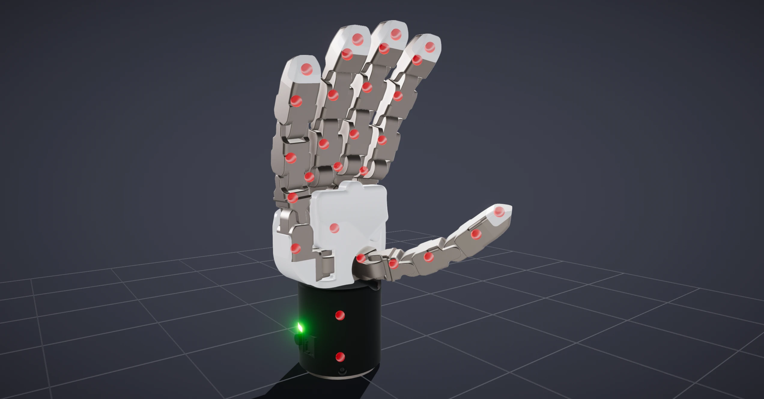
Center of Mass marks each link's center of mass with a small sphere, so you can quickly check that a link's mass sits where you expect.
Collision Geometry
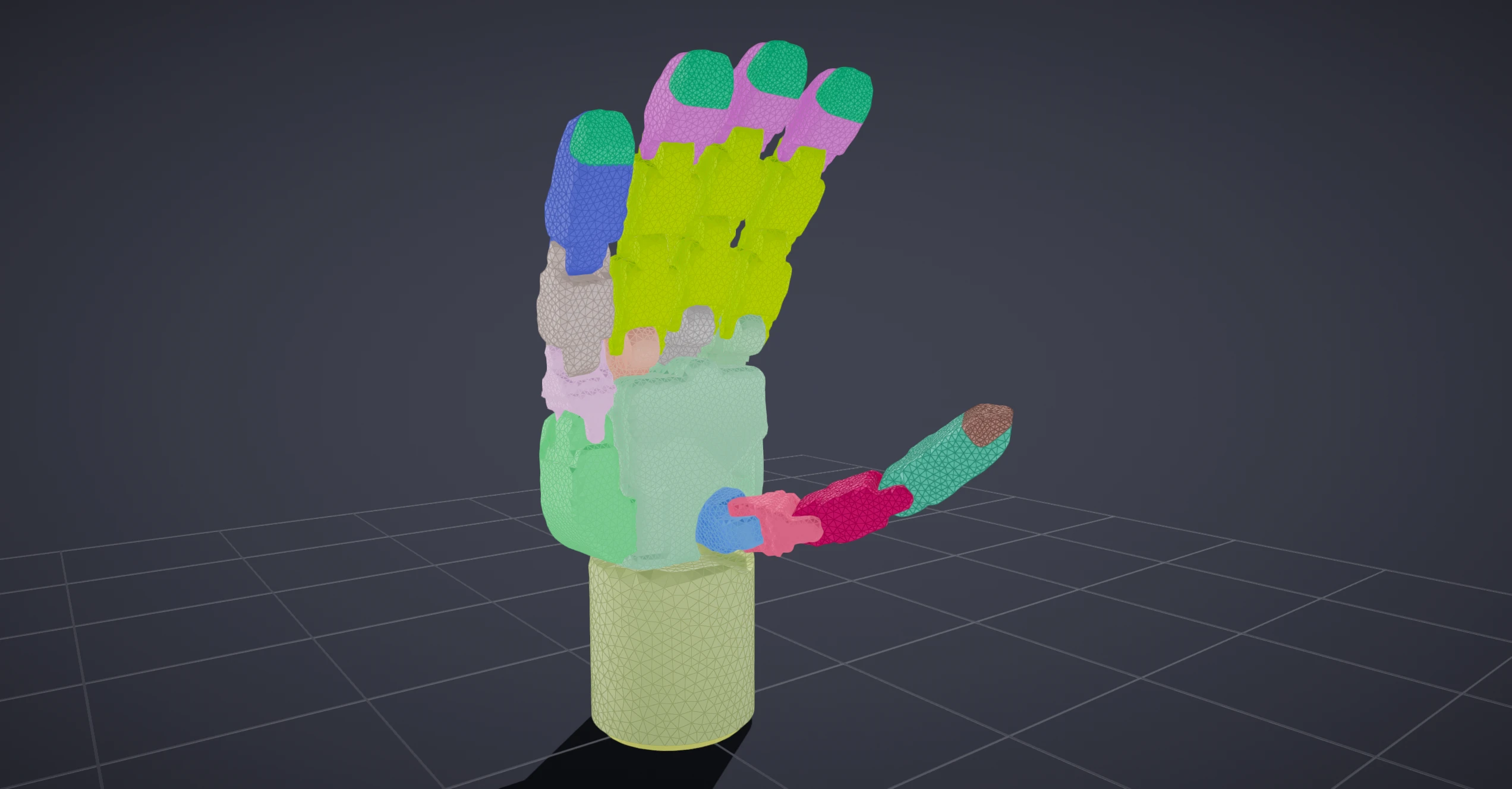
The model options at the bottom of the Show menu choose which geometry the viewport
draws. Collision Only (2) hides the render meshes and shows just the
collision meshes that SuperDex Physics simulates, each link in its own color so
neighboring parts are easy to separate. It is the fastest way to confirm the
physics geometry matches the robot you see. Render Only (1) and
Render (Collision Fallback) (3) switch back to the render meshes.
Visualization Settings
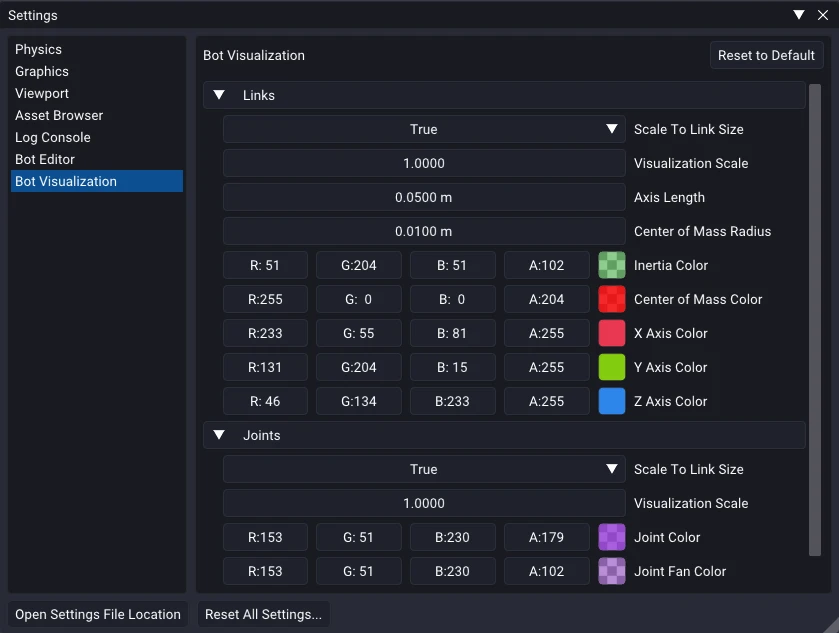
The colors, sizes, and scales these overlays use are app-wide settings. Edit them from File > Settings > Bot Visualization, where you can tune the axis length, center-of-mass radius, the inertia, center-of-mass, axis, and joint colors, and the per-link scaling for both links and joints.
Physics Debug Draw
Unlike the overlays above, which are drawn from the bot's authored data, Physics
Debug Draw is specific to a simulated scene: its overlays are fed by live
state straight from the SuperDex Physics simulation. Toggle it with P (see
Toggle Visualizations) once a simulation is running to
see contacts, bounding volumes, collision samples, and more.
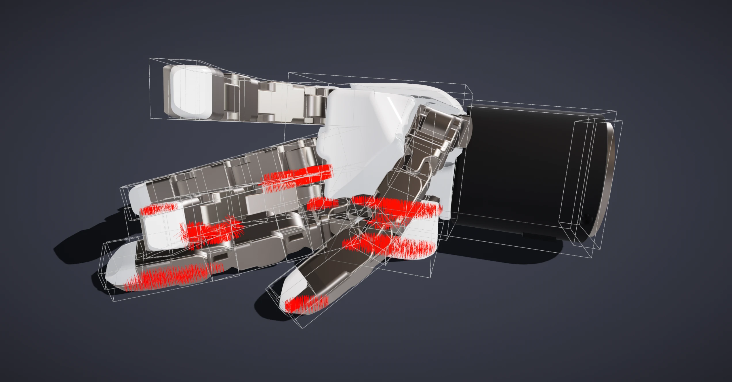
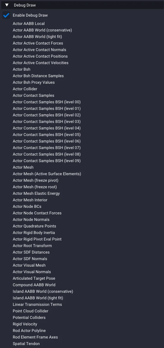
Exactly what gets drawn is chosen from a long list of toggles under Debug Draw. Open it from Window > Physics Settings > Debug Draw to change only the current editor, or from File > Settings > Physics Settings > Debug Draw to set the default that every freshly created editor starts with. Turn on Enable Debug Draw, then pick the specific quantities you want to see. The list grows over time as new debug draw features are added, so hover any entry to see exactly what it draws.
As an example, here is the Actor Active Contact Velocities overlay during a grasp, drawing the sliding velocity at each contact as the fingers settle on the object.