Model Editor
The Model Editor allows refinement of assets from one form to another.
It allows conversion of CAD and render meshes into simulation-ready collision
geometry through an ordered, editable modifier stack. Open a STEP file, stack up
a few modifiers, press Build/Export All, and get a .mochi.h5 collision
model. Processing stages are saved for your models and repeatable. Each stage is
individually available for inspection so you can refine your model further.
Creating presets so future models can use the same processing pipeline is
trivial.
Opening a Model
Double-click any CAD, render, or collision model in the
Asset Browser or in a socket associated
with a bot or prefab and it opens the Model Editor.
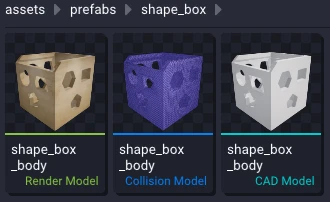
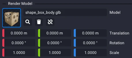
Opening a file in the model editor will search the nearby folders for a CAD, render, and collision model with the same filename and populate all 3 in the Model Viewer tab. Visuals will be enabled only for the file that was opened. Opening another file in the same set of 3 potential files will instead focus the existing tab and switch the visualization to show that file. You can manually set whatever visualization you want (even overlapping all 3 meshes to see how they compare).
| Slot | Extensions | Role subfolder |
|---|---|---|
| CAD Model | .step .stp .stl | cad |
| Render Model | .glb .gltf .dae .obj | render |
| Collision Model | .mochi.h5 | collision |
A file's type comes from its extension alone, never from the folder it sits
in. An .stl left in collision/ by a URDF import is still a CAD model, and
still feeds the mesh stack as one.
Filename Matching
Studio associates models by exact file name excluding extensions. Open
block.step and it looks for a render model with filename block and a
collision model with filename block to fill the other two slots. Base names
are compared case-insensitively, so a Block.glb still pairs with block.step.
Everything is anchored on the asset's base folder (the folder generally holding a bot or prefab file). A model inside a role subfolder (or child thereof) resolves to that folder's parent; anything else resolves to itself. This means we support 2 standard layouts for model editing. Other file and folder organization structures work but will present friction.
- Role-subfolders —
cad/,render/,collision/beside the asset file. - Flat — every model directly in the base folder.
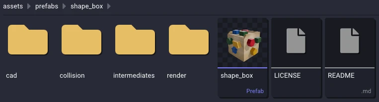
The rules behind the filename matching ensure that for any given filename there can only be 3 primary associated models. Opening any one of those models will always find the same other two if they exist. Multiple models of the same role and filename will result in the extra models being shadowed by the primary model.
For each empty slot, Studio searches in a fixed order and takes the first hit as the primary model for that slot:
| # | Where it looks | How |
|---|---|---|
| 1 | <base>/<role subfolder for that type> | Searched as a tree, breadth-first — a partitioned role such as cad/subpart_A/ still resolves, shallowest match winning |
| 2 | <base> | Flat, no descent |
| 3 | The folder the opened file actually sits in | Flat, no descent |
| 4 | The remaining role subfolders, plus the visual / visuals aliases a URDF tree uses | Trees; requires a unique hit |
Step 4 is the fallback for models filed under a role that does not match their type. For example, the URDF that imported STL files into the collision folder. Because those folders have no precedence among themselves, if there are two or more candidates none will be selected and the collision logged.
intermediates/ is never searched. It holds generated output, which must not
shadow the real asset.
When one folder holds the same base name in two formats of a single type
(block.glb beside block.obj), the winner is decided by format preference and
then by path. The preference order matches the table above in
Opening a Model from left to right.
Shadowed Models
Each filename can have only one primary file. If two files share the same name but live at different path depths (e.g. render/block.glb and render/internal/block.glb), the shallower one wins, it becomes the primary, and the deeper one is shadowed.
If you open a shadowed file like render/internal/block.glb, Studio will open it on its own with the other slots empty, and report a shadowed warning in the Log Console. The shadowed copy never pulls in models that belong to the primary set.
Shadowed files still save their Model Editor state, but do so under intermediates/ in folders that mirror their path relative to the base folder. For example, intermediates/render/internal/block.glb.StudioProcessing.json.
You can still work with shadowed files by adding them as a reference model for viewing, or pointing a source modifier's slot at them for processing.
Editor Windows
The Model Editor adds two windows to the Studio frame, both open by default.
| Window | What you do there |
|---|---|
| Model Viewer | The three model slots, their visualization controls, and the reference models. Docks top-right. |
| Model Processing | The mesh processing modifier stack. Docks bottom-right. |
The Model Editor viewport has no ability to simulate. It is for modifying mesh assets which do not contain the necessary parameters for simulation. The camera controls and the viewport overlays work as they do everywhere else (covered in User Interface).
The Model Editor does not yet have a built-in undo stack. This will be coming very soon.
Model Viewer
The Model Viewer only allows viewing multiple models together. One collapsing section per role, each with an asset slot, a color picker, and its own Surface / Wireframe / Stats toggles and opacity slider. A section opens expanded by default when its slot is filled and collapsed when empty.
Only the model you actually opened has its visualization toggles enabled. Slots filled by discovery stay hidden until you tick them on, so opening a STEP shows you the STEP rather than three overlapping meshes. Opening another file in the same set will focus the window and update the visualization toggles to show that new file. A collision model opens with its surface and wireframe on; CAD and render models open with surface only.
The three fixed slots are view/reference-only. They are bound to the filename set, so they take no drag-and-drop and have no clear button. To bring in a mesh that is not part of the set, use a reference model for visualization or a source modifier's slot for processing.
CAD Model
Holds a STEP or STL CAD model. An STL is read directly; a STEP is tessellated in the background with fixed default deflections to give you something to look at. This preview is independent of the modifier stack, which has its own tessellation settings — Generate here only re-reads and re-tessellates the preview.
The section also carries the CAD transform: a scale, rotation, and translation applied to the imported CAD geometry. Editing it re-applies to the cached tessellation immediately, with no re-tessellation. The transform is baked into any CAD source modifiers. The transform is saved as part of the Model Editor state.
Render Model
Holds a .glb / .gltf / .dae / .obj render model. The surface keeps
materials and textures unless you tick Override with color or drop the
opacity below 1.0, either of which swaps it for a flat material in the color
picker.
OBJ material colors are read (one section per material), but image textures are not currently handled.
Collision Model
Holds a .mochi.h5 collision model. This contains the data that our physics
engine simulates with. The section shows two things:
| Sub-section | What it draws |
|---|---|
| Mochi Model Visualization | The collision surface mesh stored in the file. |
| SDF Visualization | The surface reconstructed from the file's baked signed distance field, in its own color. Disabled when the model has no SDF. |
Both the surface model and SDF have an impact on the simulation with the surface mesh of one model colliding with the SDF of another and vice versa. The relative modeling error between the two influences how collision resolves so it is useful to be able to visualize both independently. The SDF visualization is implemented through a marching cubes algorithm.
Additional Reference Models
Below the three fixed slots (CAD, Render, Collision), Additional Reference Models is a user-managed list of extra models to show alongside them. Use the reference models to visualize any asset you currently have alongside the primary models. All reference models and their state are saved as part of the Model Editor state and will automatically be opened when opening the associated file.
When adding an entry select a type (CAD Model, Render Model, Collision Model), then populate the asset slot by drag-and-drop from the Asset Browser or selecting it from the path dropdown. You can configure the visualization parameters to your liking and set a transform to offset and orient the model. The UI allows you to add to the top or bottom of the array of models, remove any of them, and drag to reorder.
Reference models are visualization context only. They are deliberately not reachable by the processing modifiers and are never offered as a source.
To feed a mesh into the pipeline that is not part of this model's filename set, add a source modifier and set its Method to From File.
Mesh Statistics
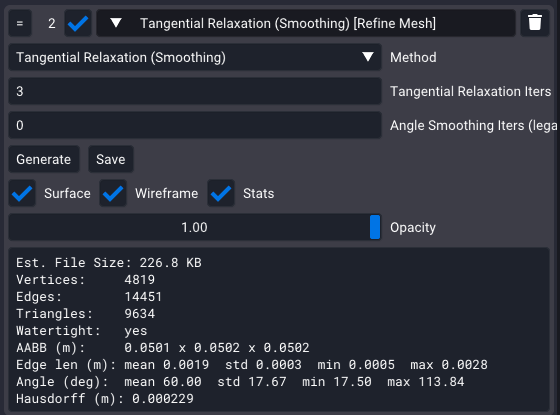
Every slot, stage, and reference model has a Stats toggle that opens a read-only, copyable summary of its geometry:
| Line | Meaning |
|---|---|
| File Size / Est. File/Export Size | The file on disk, or an estimate of what a stage would write |
| SDF grid | Baked SDF grid dimensions, if one is present |
| Vertices · Edges · Triangles | Counts for the geometry as displayed |
| Watertight | Whether the surface is closed/watertight |
| AABB (m) | Bounding-box size, in meters |
| Edge len (m) / Angle (deg) | Mean, standard deviation, min and max |
| Hausdorff (m) | For a stage: approximate distance from its input mesh to its output mesh (how much the modifier altered the surface) |
The Hausdorff distance is computed in the background and appears when it is ready; a superseded or removed stage's result is discarded rather than shown against fresh geometry.
Saved Pipelines
Every widget set in the Model Editor is saved per model, as a human-readable JSON file. The only exclusion is the visualization options for the three fixed slots.
The path for primary filename sets is:
<base>/intermediates/<model base name>.StudioProcessing.json
intermediates/ is always a subfolder so it stays out of the way. This works
well with both the role-subfolder and flat organization schemes. The
intermediates/ folder is intended to contain saved and generated content.
Saving any intermediates from your processing pipeline will default to
intermediates/.
Studio writes the file on generate, on build, on close, and after each discrete edit — but only when something actually changed, so opening and closing a model without editing it never touches the file. If the editor is reset to a clean state (no modifiers, no reference models, identity CAD transform) the save will be deleted rather than left behind empty.
Every stored path is written relative to the JSON file, so the document carries no absolute paths and survives being copied to another machine or another asset. A modifier or method that Studio does not recognize is preserved verbatim and written back out unchanged, so a file from a newer build is not silently truncated by an older one.
If the file cannot be parsed on open, Studio starts with an empty stack, says so in the Log Console, and blocks saving for that filename so it cannot clobber a file you may still want to fix by hand.
Model Processing
The Model Processing window holds the processing pipeline, an ordered stack of modifiers. Each modifier represents a named group of related methods to modify the mesh. For example, the modifier Refine Mesh contains the methods to help refine the existing mesh like making it watertight or collapsing small edges.
Modifiers come in three kinds, tinted in the stack so they can be identified at a glance:
| Kind | Tint | What it does |
|---|---|---|
| Source | Blue | Produces geometry from a file. Ignores whatever is above it. |
| Transform | Grey | Consumes the output of the nearest enabled modifier above it, and produces a new mesh. |
| Export | Orange | Writes its input mesh to a file. Passes the mesh through unchanged. |
A source has to come first, so the chain always has an input: anything sitting above the first source is skipped when the stack runs, and a non-source cannot be dragged to the top.
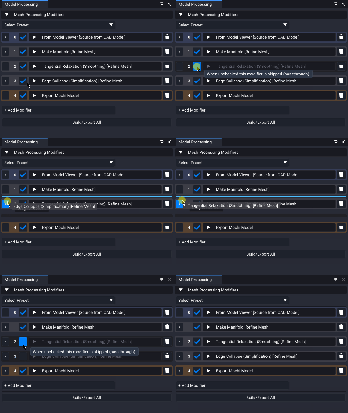
Add modifiers with + Add Modifier, drag the = grip to reorder, untick the
checkbox to skip a modifier as a passthrough, and use the trash icon to remove
it. A modifier that has only one method implemented shows no Method dropdown.
Presets
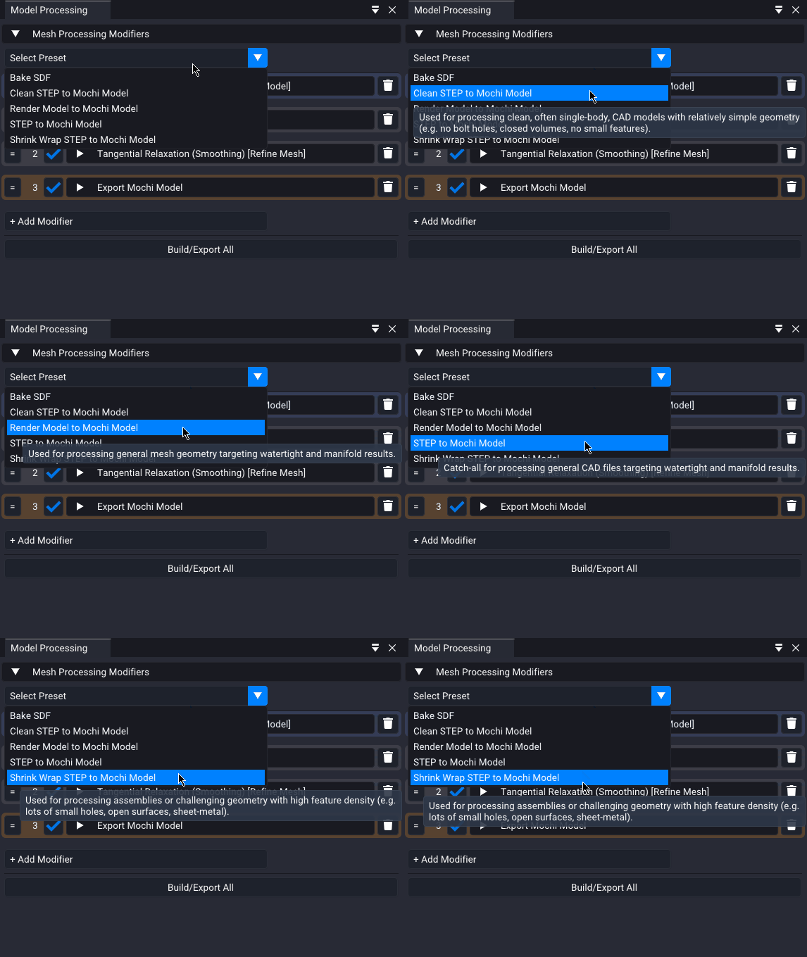
A preset is a ready-made pipeline you can drop onto any model. Select Preset is found at the top of Model Processing. Studio ships with several built-in pipelines but you can add your own trivially. Picking one replaces the current stack, asking first if the stack is not empty.
| Preset | Reach for it when |
|---|---|
| STEP to Mochi Model | Catch-all for general CAD, targeting watertight and manifold results |
| Clean STEP to Mochi Model | Clean, often single-body CAD with simple geometry — no bolt holes, closed volumes, no small features |
| Shrink Wrap STEP to Mochi Model | Assemblies or challenging geometry with high feature density — lots of small holes, open surfaces, sheet metal |
| Render Model to Mochi Model | General mesh geometry rather than CAD, targeting watertight and manifold results |
Adding Your Own
Presets are just saved pipeline documents in a specific location. They are of the same format the editor already saves. To add one:
- Build the stack you want on any model and let Studio save it.
- Copy that model's
.StudioProcessing.jsoninto theprocessing_presets/folder next to the Studio executable. - Rename it to what you want in the menu. The file stem is the display name,
with underscores shown as spaces, so
Shrink_Wrap_STEP_to_Mochi_Model.jsonreads as Shrink Wrap STEP to Mochi Model. - Optionally add a top-level
"description"string for the tooltip.
Presets are picked up on each open of the dropdown and listed alphabetically, so
no restart is needed. Point MOCHI_STUDIO_PRESETS_DIR at another folder to
override where Studio looks.
Two details make a preset portable. The preset is applied to the current open
filename, meaning all relative paths in the preset apply to the model it is
applied to, not against the preset's own location. Export paths defaulting to
Auto will recompute based on the current open filename. And saving still
targets the model's own intermediates/ file (applying a preset never writes
back to the preset).
For the most widely usable presets, Sources should pull their mesh From Model Viewer and Exports should use an Auto path.
Sources, Processing, Export
The stack is written with data flowing from the top to the bottom:
Source → Refine / Wrap / Remesh / Transform → Export
A Source Modifier pulls its input data from outside the processing pipeline. Each Transform Modifier below it reworks the mesh one stage at a time. An Export Modifier writes the mesh to the disk and passes its input through. Pipelines can be as complex or simple as you would like. We explicitly chose not to make the processing an arbitrary node graph of connections to make it more tractable and usable. Supplementing your processing with other tools like the SuperDex CAD Exporter or Blender/Maya will enable you to do whatever you want.
An export in the middle of the stack is a checkpoint, not an end. That is what makes the stack a conversion and refinement pipeline rather than a one-shot: because a source reads a file and ignores the stage above it, a stack may hold several segments end to end.
Source (STEP)  →  remesh  →  Export (.mochi.h5)
Same Source    →  remesh  →  Export other collision
Same Source    →  remesh  →  Export other collision
or
Source (STEP)  →  refine  →  Export (.glb)
Source (.glb)  →  remesh  →  Export (.mochi.h5)
Build/Export All processes each stage of the pipeline in sequence. Exports are done as part of their modifier stage so each following source can pick up what the export above it just wrote.
Coordinate spaces are handled for you. The formats disagree about which axis is
up - .obj, .stl and .mochi.h5 are authored Z-up. A .obj, an .stl, a
.glb and a .mochi.h5 of the same part all land in the same orientation after
processing. The Axis Gizmos provided in superdex_studio/assets/axis_gizmos/
are a useful tool to verify orientation. They have been carefully authored to be
consistent.
Generating and Building
There are three ways to run the stack, all of them stale-aware: a stage that is already up to date is skipped, and one that is not is rebuilt first.
| Control | Where | What it runs |
|---|---|---|
| Generate | On any modifier | That modifier, plus any stale stages above it — back to the nearest preceding source. Its own segment only. |
| Export | On an export modifier | Generates as above, then writes that modifier's input mesh to its configured file. |
| Build/Export All | Bottom of the window | Generates and Exports each modifier in sequence from the first enabled source down the pipeline. |
A stage is stale when it has never generated, when its own parameters or method changed, or when a mesh it derives from has been regenerated since. Staleness cascades downstream. A source is the exception, it builds from a file, so it neither inherits the cascade nor tracks the stage above it; instead it rebuilds if it has not or when an export preceding it in the pipeline has written.
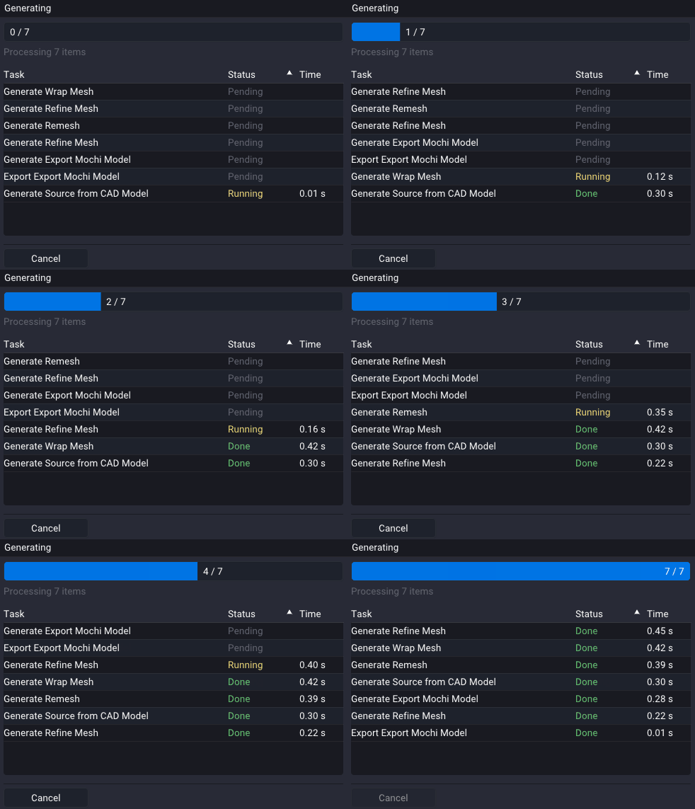
Everything runs on a background thread behind a cancelable progress dialog, and reports its state to the Log Console. If a stage fails, the failure propagates: later stages get no input and stop, rather than quietly running on errored geometry. Exports already written above the failure stay written.
The staleness detection does not detect file changes outside Studio between runs. Press Generate on the source to pick it up.
Clicking cancel will cancel all remaining tasks but cannot interrupt already executing tasks that do not have cancel points. Some functions like Bake SDF in the Export Mochi Model Modifier do not yet have proper checkpoints. So a long running Bake SDF call can be canceled before it starts but will fully run before stopping if cancel is clicked during its execution. This will be addressed soon to make the cancel button feel very responsive.
Export Paths
All export modifiers derive their output path from the source file while Auto is ticked:
| Export | Auto path |
|---|---|
| Export Mochi Model | <base>/collision/<name>.mochi.h5 |
| Export Mesh File | <base>/render/<name>.glb |
Export Mesh File can export either `.glb` or `.obj` if the path is specified.
When using a role-subfolder organization the target folder is used whether or
not it exists. It is created on write. Exporting a STEP opened from cad/ fills
render/ and collision/ rather than dropping files beside the STEP. A flat
folder organization stays flat.
Pressing Browse takes the path over and turns Auto off. You can also manually uncheck the Auto populate checkbox. The path is saved only if the Auto checkbox is off. Two enabled exports aimed at the same file warn inline and in the log, since one would silently overwrite the other. Alter one of the paths to be different.
Inspecting a Stage
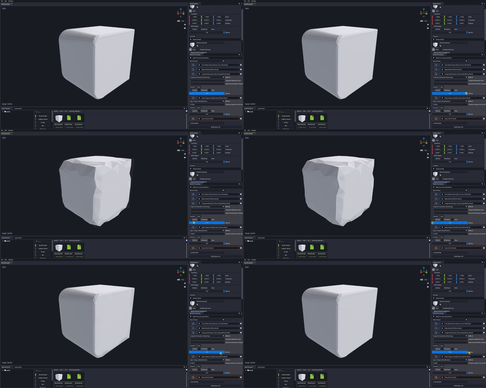
Every modifier keeps its own output buffer, with the same Surface / Wireframe / Stats / Opacity view controls as in the Model Viewer. Visualize two stages at once to see exactly what changed.
Export Mochi Model shows both the surface mesh and SDF that was generated as part of the modifier.
Save, on each modifier next to Generate. Saves the modifier's current output
to a .glb or .obj for inspection. This defaults into the asset's
intermediates/ folder and matches the filename with a suffix based on the
Modifier and pipeline ordering. This is incredibly helpful if you need to
inspect the processing stage in another tool or as reference for another model.
Modifier Reference
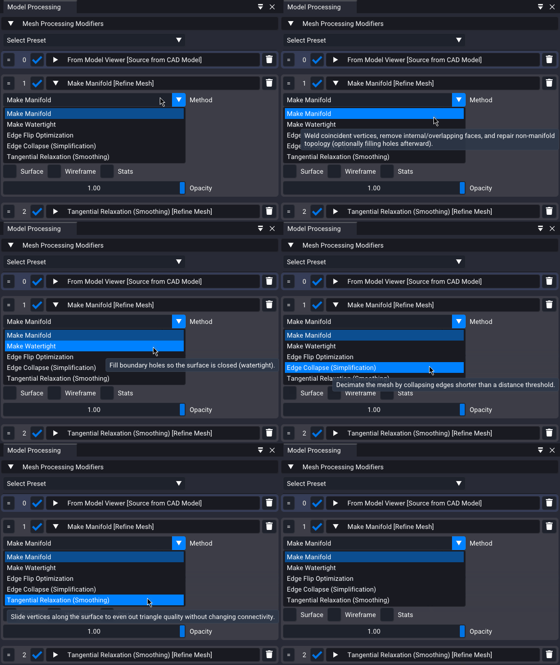
Every method's parameters carry hover tooltips in the app, which are the authoritative reference. Below is a simple description of each modifier and method currently available.
Sources
Every source offers the same two methods. From Model Viewer uses the opened 3 primary slots from the Model Viewer. From File carries a slot of its own, independent of the Model Viewer, and is how you specify a file directly.
Source from CAD Model
| Method | What it does |
|---|---|
| From Model Viewer | Uses the editor's current CAD Model slot. A STEP is tessellated with the options provided; an STL is read directly. |
| From File | The same, from this modifier's own CAD slot. |
Source from Render Model
| Method | What it does |
|---|---|
| From Model Viewer | Uses the editor's current Render Model surface. |
| From File | The same, from this modifier's own render slot. |
Source from Mochi Model
| Method | What it does |
|---|---|
| From Model Viewer | Uses the editor's current Mochi Model surface. |
| From File | The same, from this modifier's own collision slot. |
The CAD source is the only one with tessellation settings, and they only appear when the slotted file is a STEP. Two backends for this tessellation are available:
| Backend | Character |
|---|---|
| Isotropic (CGAL) | Constrained Delaunay triangulation over uniformly sampled points on each CAD face. Highest quality on simple CAD, and prioritizes uniform edge length. |
| Delabella (OCCT) | OpenCascade's fast BRepMesh, aiming for visual fidelity. Remeshing afterwards is strongly recommended for physics. |
Both take a linear and an angular deflection. The Isotropic backend adds control over solid combining, edge sampling (use Adaptive to preserve round holes and fillets), target edge length, and whether to keep going when a face fails to tessellate.
Transforms
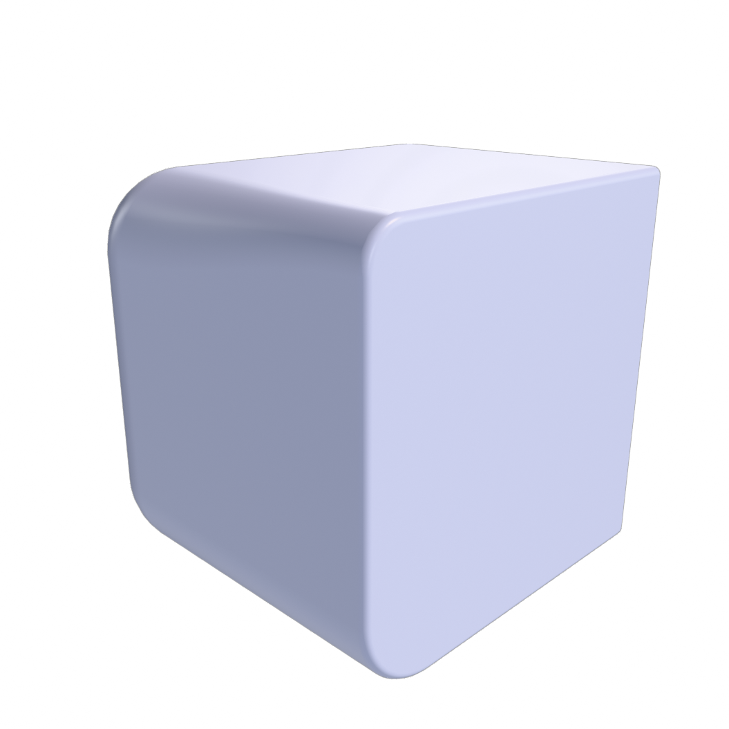
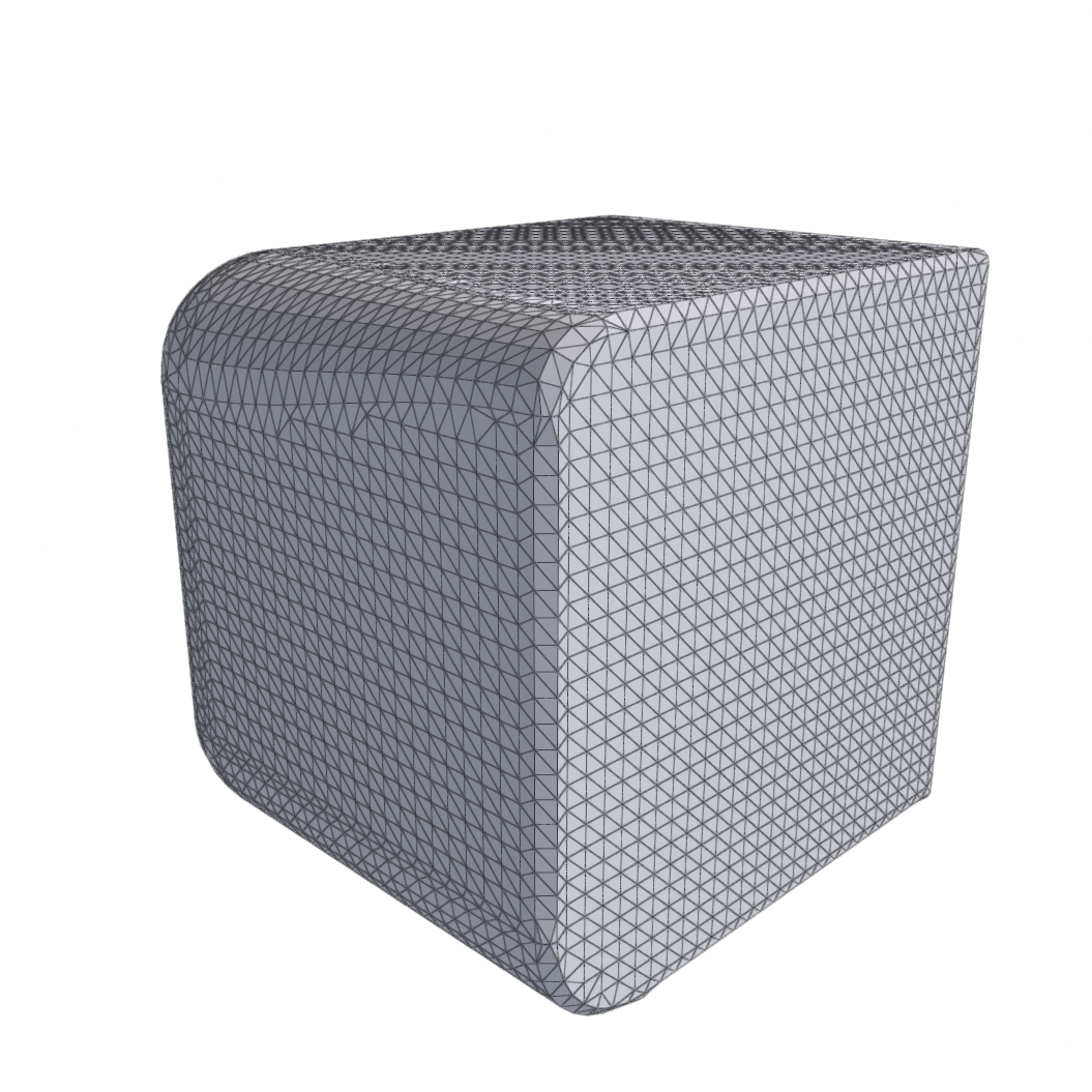
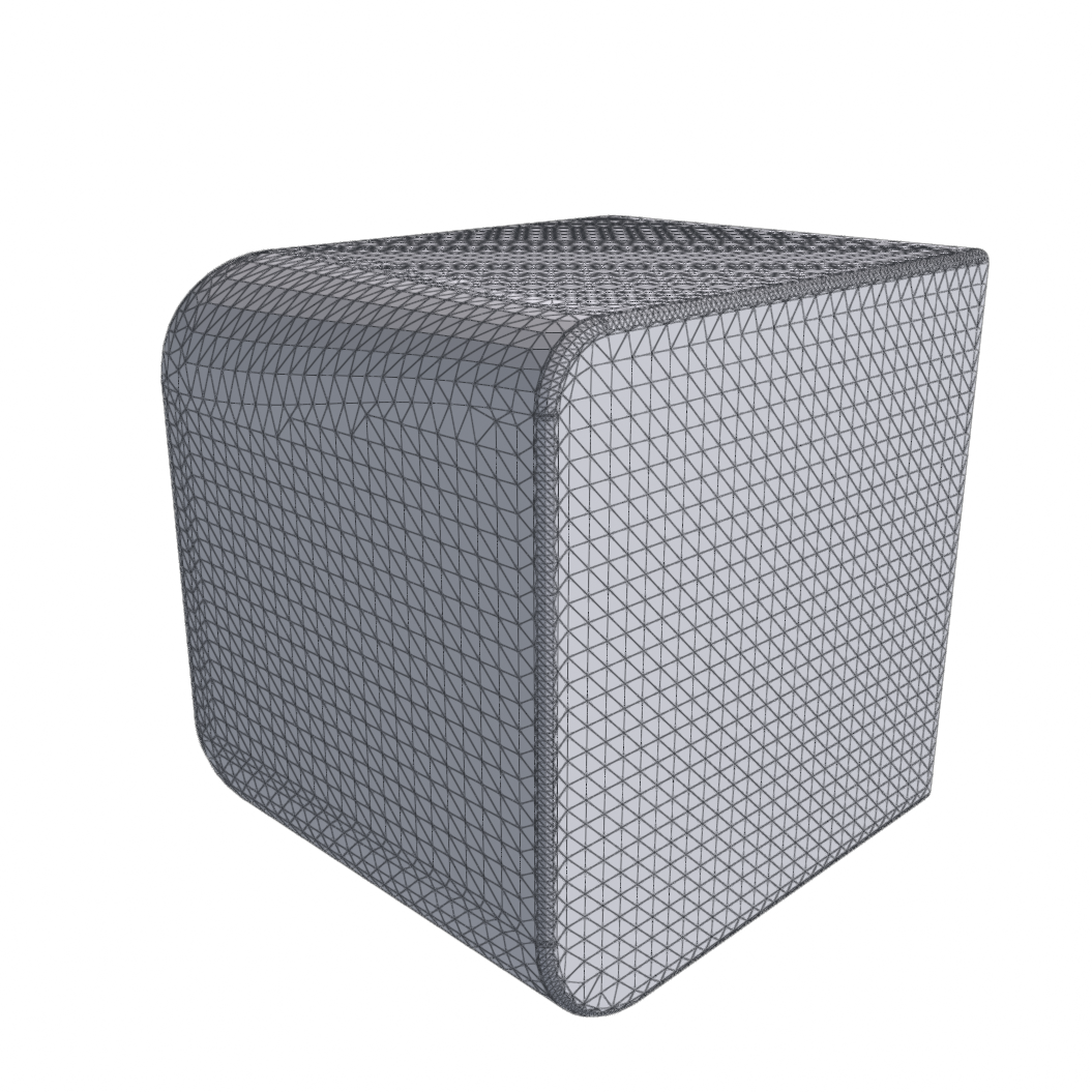
Refine Mesh
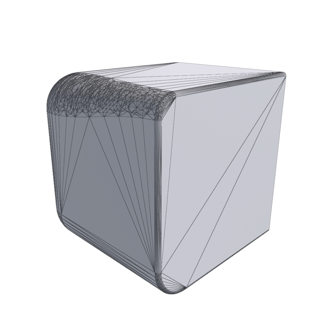
Local mesh-quality operations that keep the mesh on, or near, its input surface.
| Method | What it does |
|---|---|
| Make Manifold | Weld coincident vertices, remove internal and overlapping faces, and repair non-manifold topology — optionally filling holes afterwards. |
| Make Watertight | Fill boundary holes so the surface is closed. No parameters. |
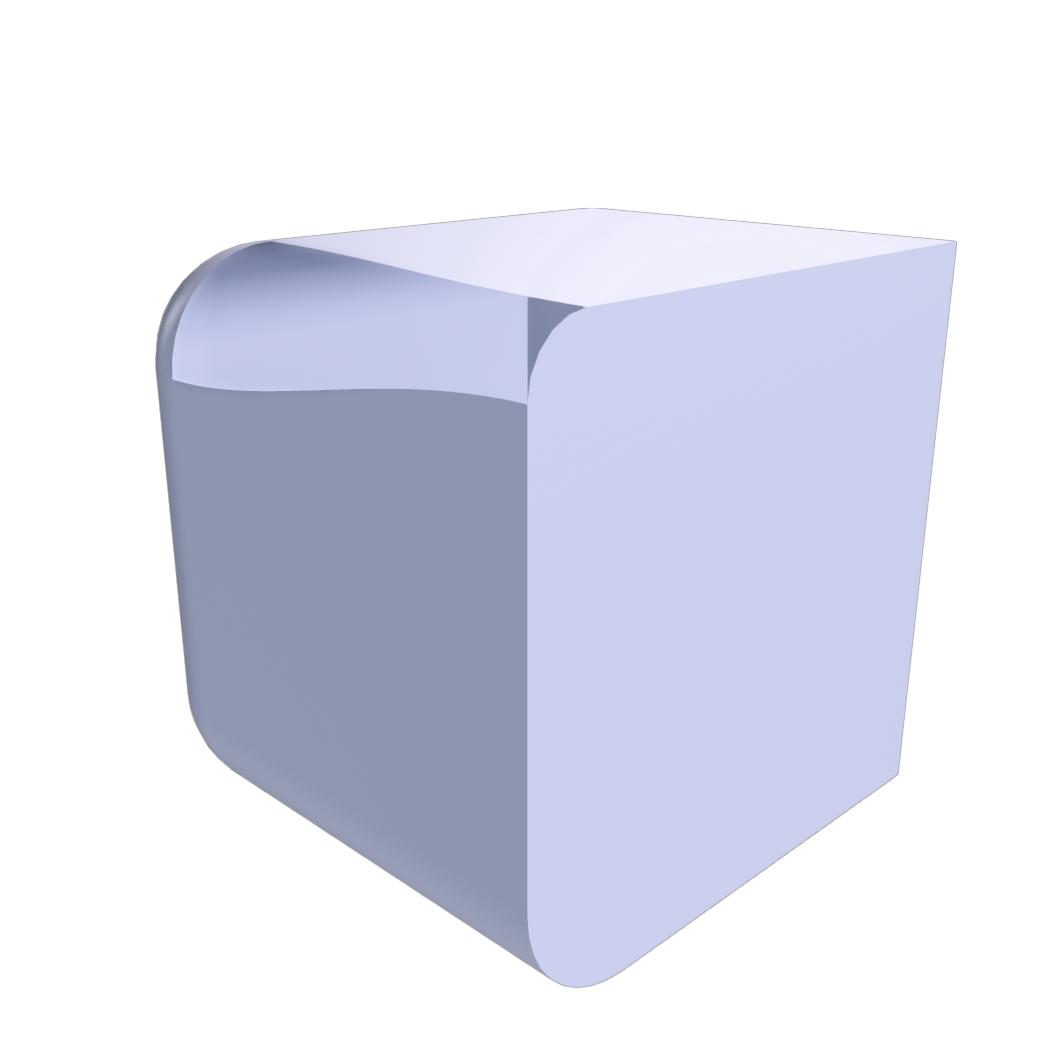
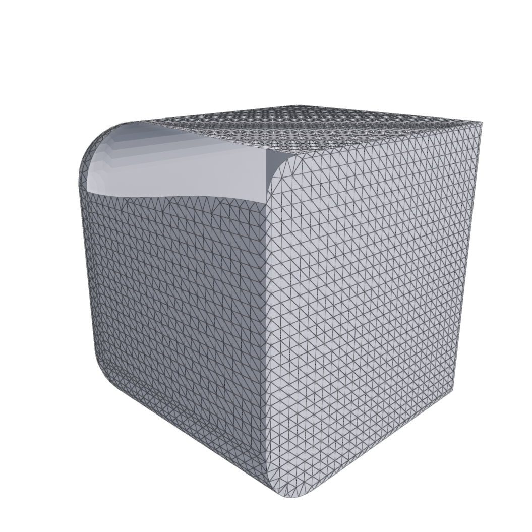
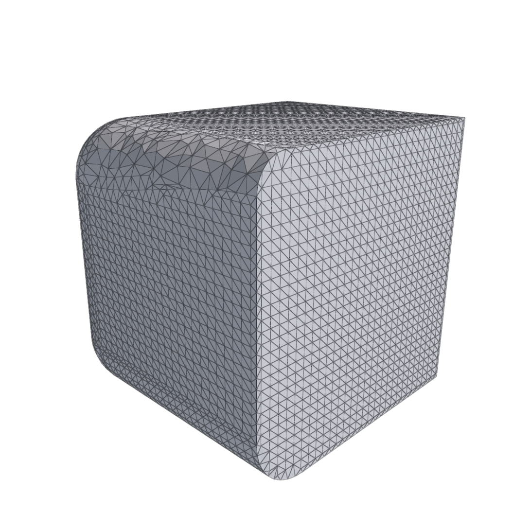
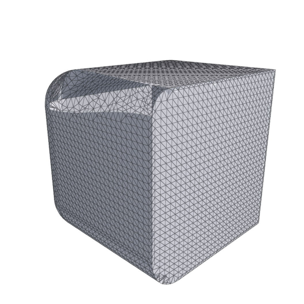
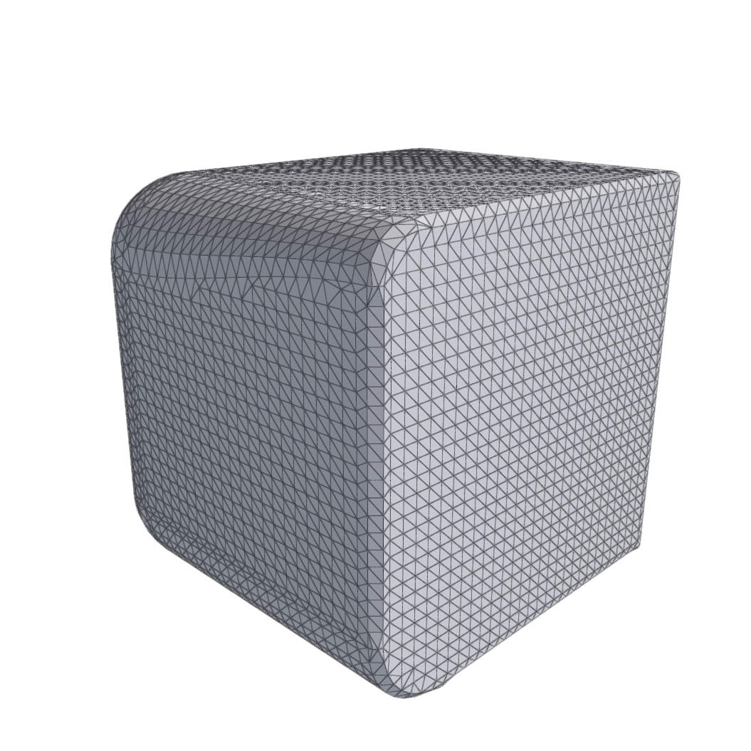
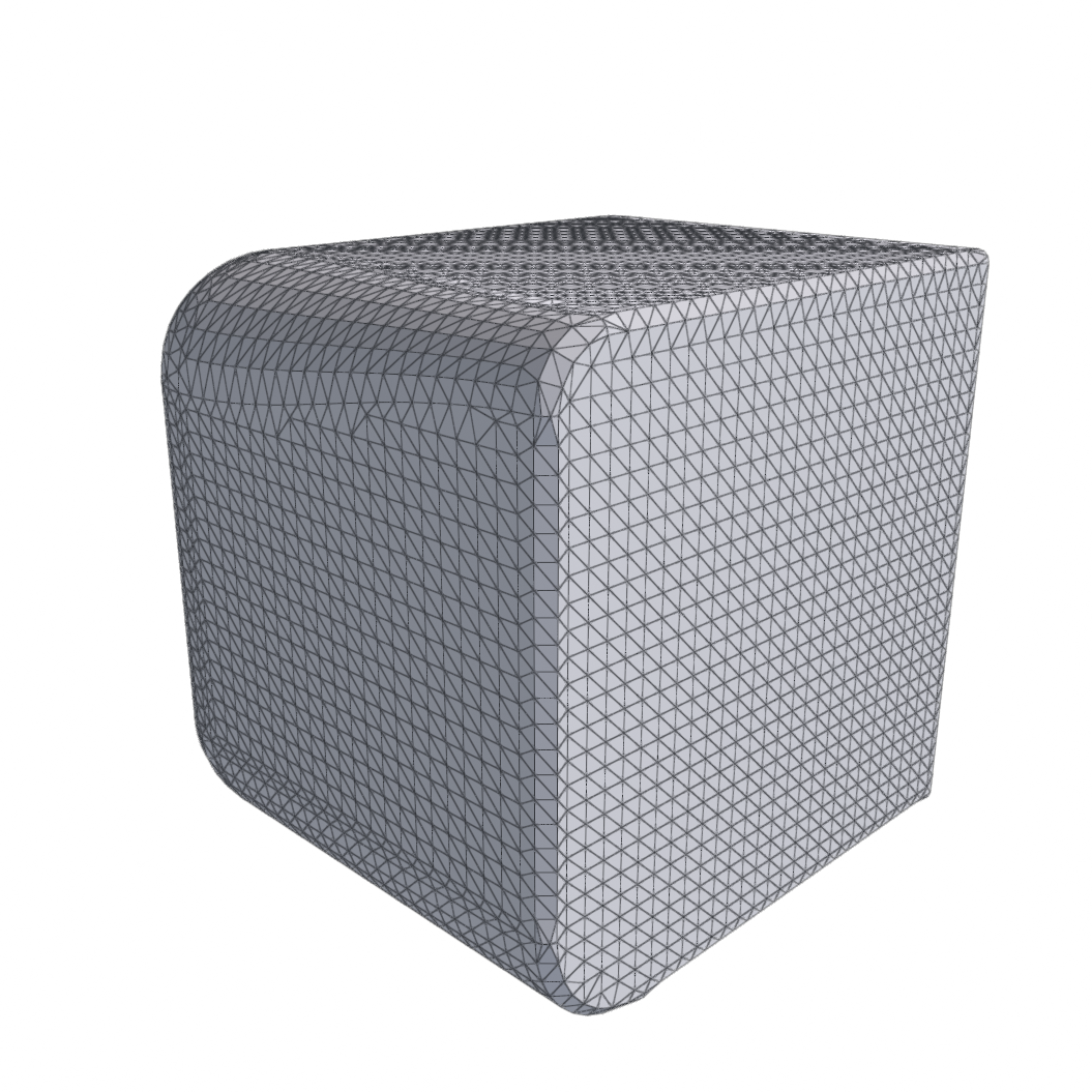
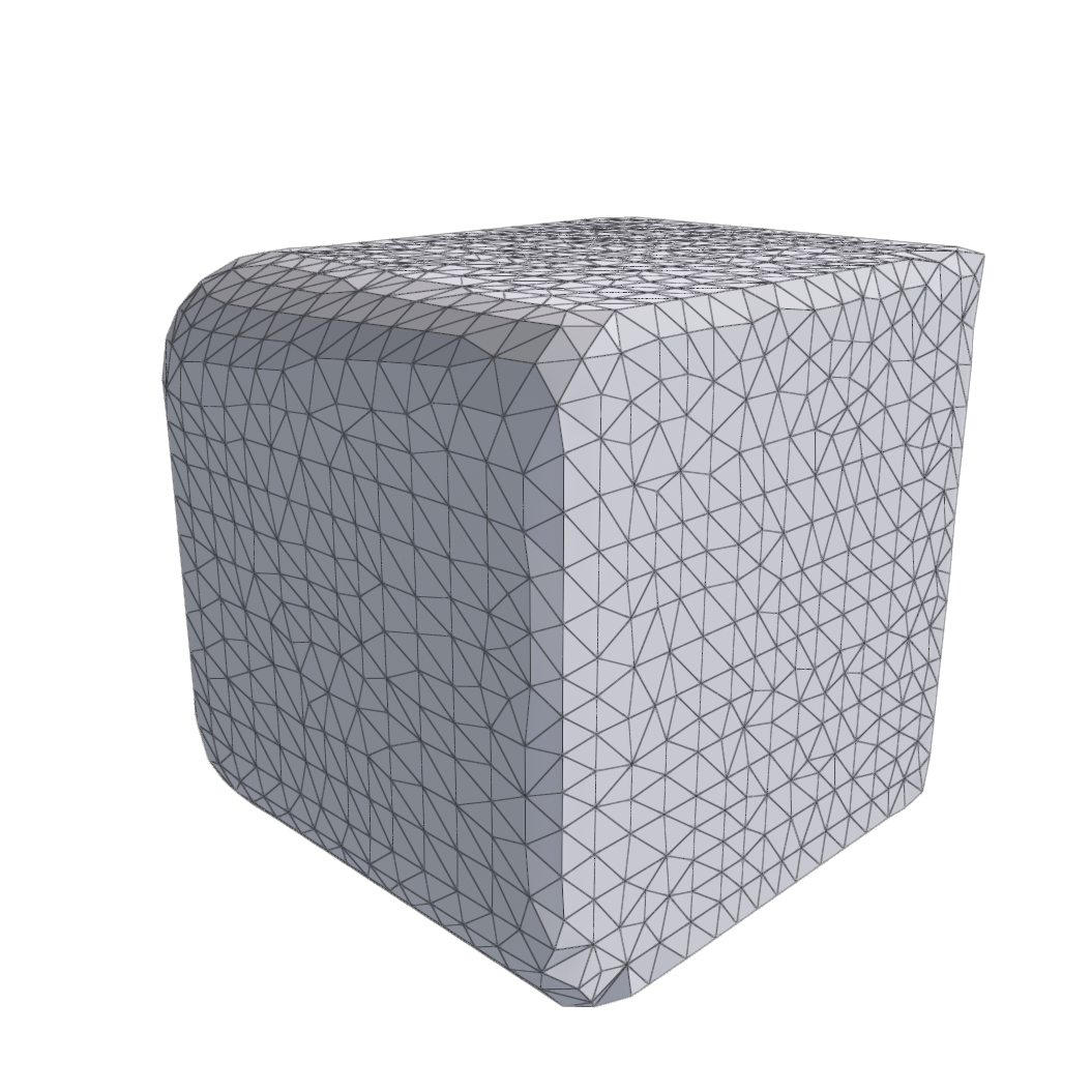
| Edge Flip Optimization | Retriangulate by flipping edges to better fit an upstream reference surface, leaving vertex positions unchanged. |
| Edge Collapse (Simplification) | Decimate the mesh by collapsing edges shorter than a distance threshold. |
| Tangential Relaxation (Smoothing) | Slide vertices along the surface to even out triangle quality without changing connectivity. |
Edge Flip Optimization takes in a second mesh reference so that it can
optimize the edge flips to get closer to its reference mesh. Its Reference
dropdown defaults to the Preceding Source, but you can specify an earlier
stage by index. References follow their targets through reorders, inserts, and
deletes. If you move the Edge Flip Optimization above its reference it will read
(invalid source) and fail until a valid source is picked.
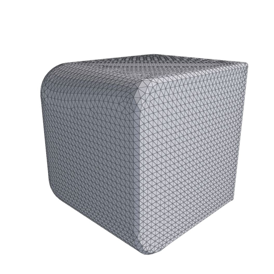
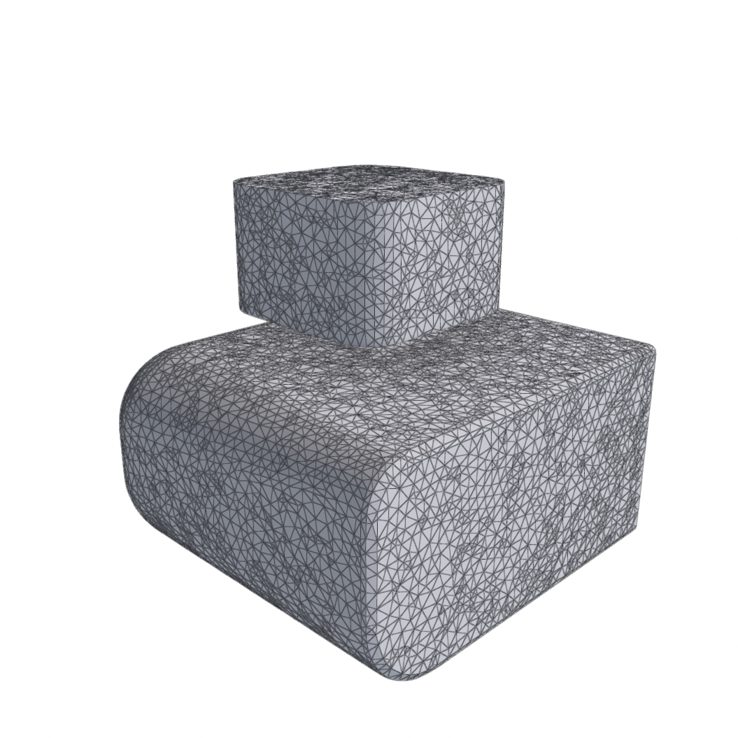
Wrap Mesh
Builds a fresh closed envelope around the input rather than repairing it. Reach for these when the input is too broken to refine.
| Method | What it does |
|---|---|
| Shrink Wrap | Shrink a hull onto the surface to build a watertight envelope, bridging concavities and covering holes. |
| Convex Hull | Replace the surface with its convex hull, remeshed. No parameters. |
| Alpha Wrap | Alpha-wrap the surface into a watertight envelope; alpha sets the finest detail captured. |
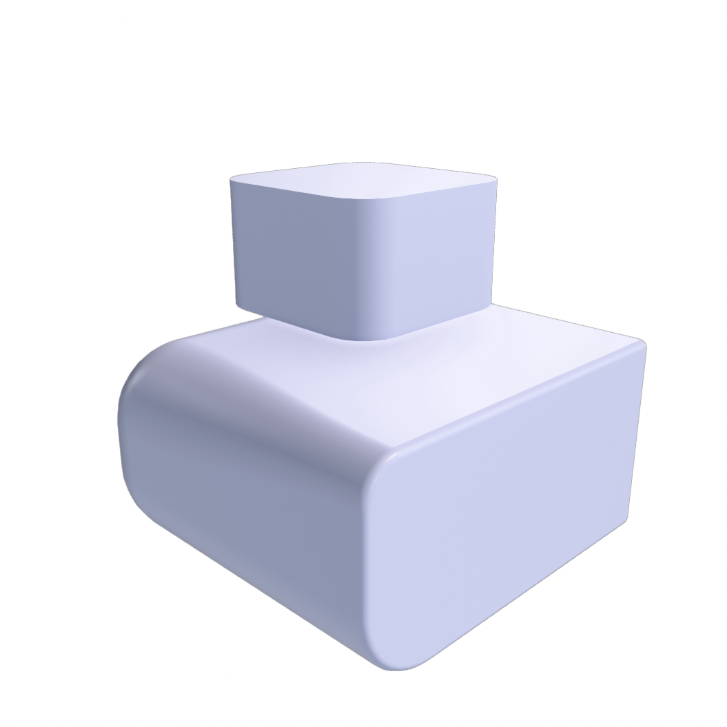
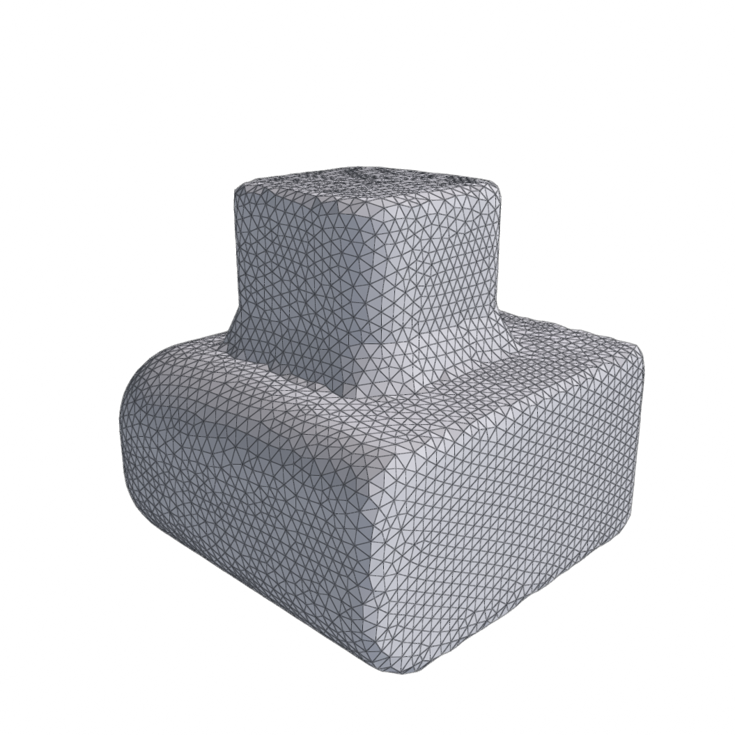
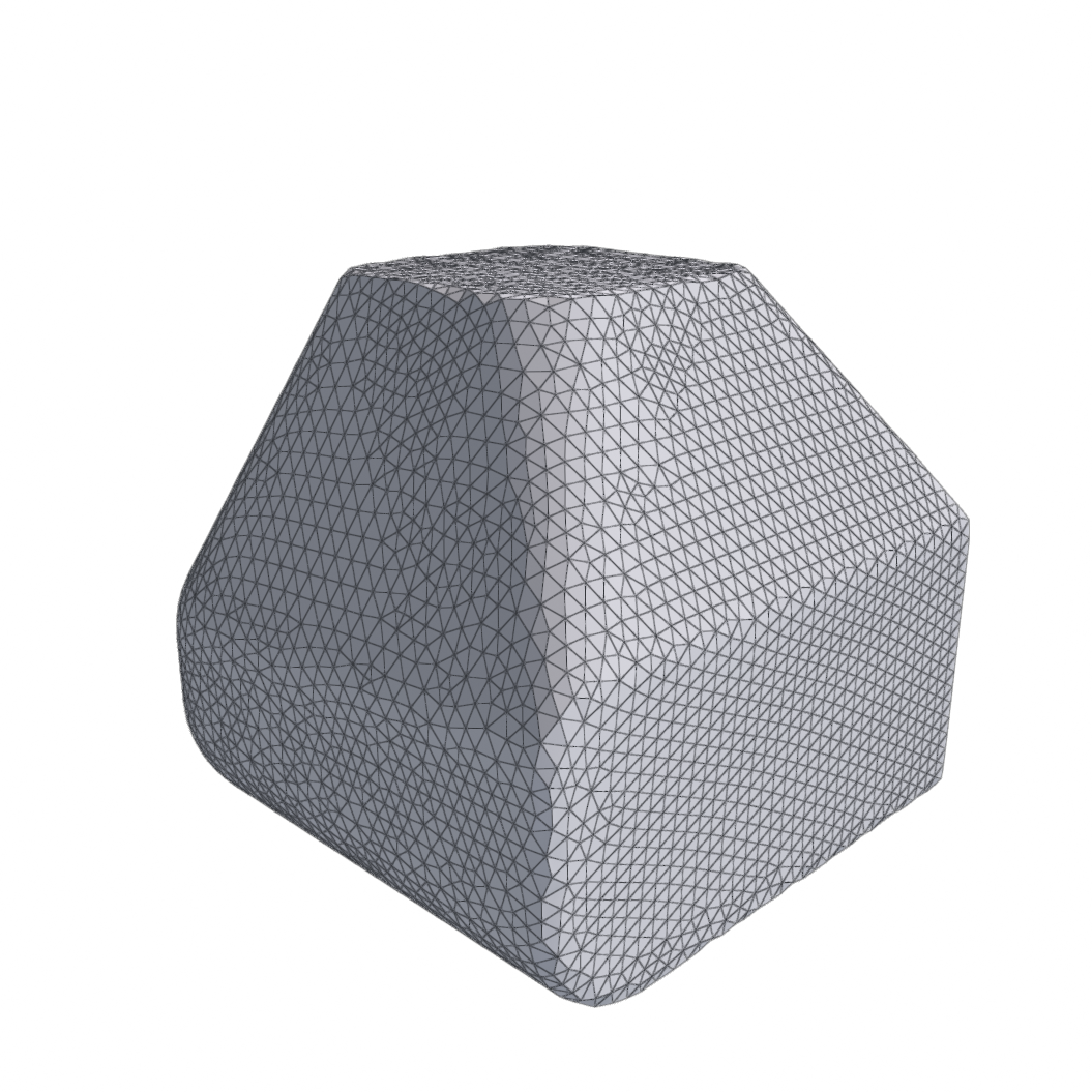
Remesh
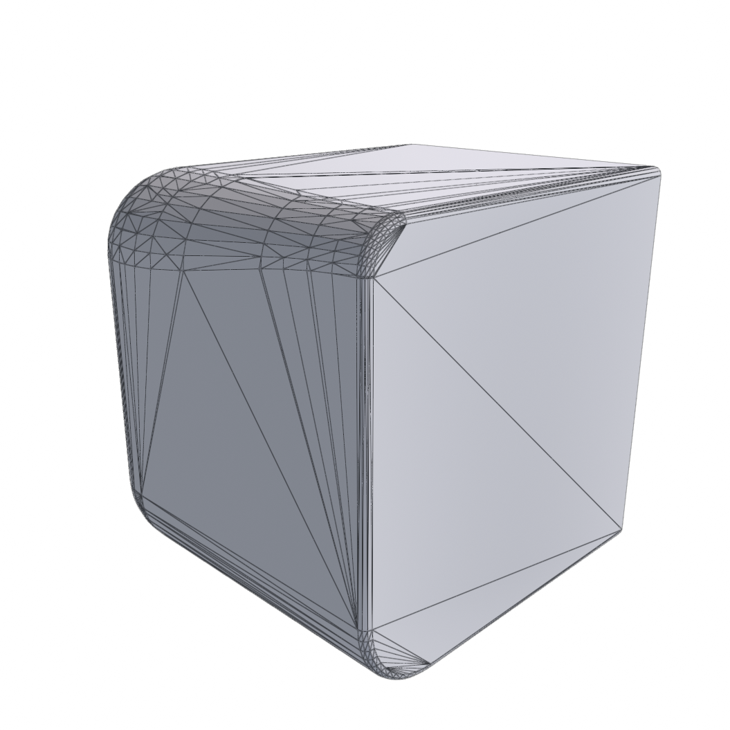
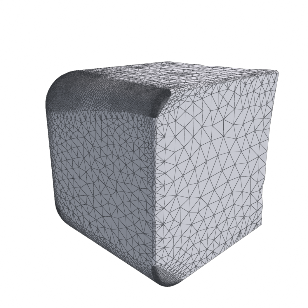
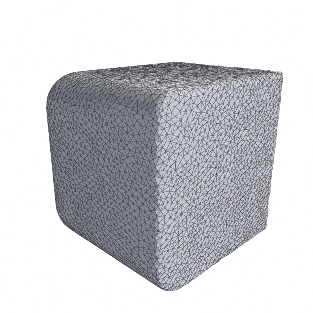
Rebuilds the triangulation while staying on the input surface.
| Method | What it does |
|---|---|
| Approx Centroidal Voronoi Diagram (ACVD) | Resample toward a target vertex count via ACVD clustering. Fills holes first. |
| Surface Delaunay Triangulation | Resample with Delaunay refinement bounded by facet angle and distance. Fills holes first. |
| Incremental Isotropic Remesh | Iteratively split, collapse, flip, and relax edges toward a uniform target edge length. |
ACVD and Surface Delaunay require a closed input, so both fill holes before they run. Isotropic remesh can take any input mesh, and is your best brute force solution for bad meshes.
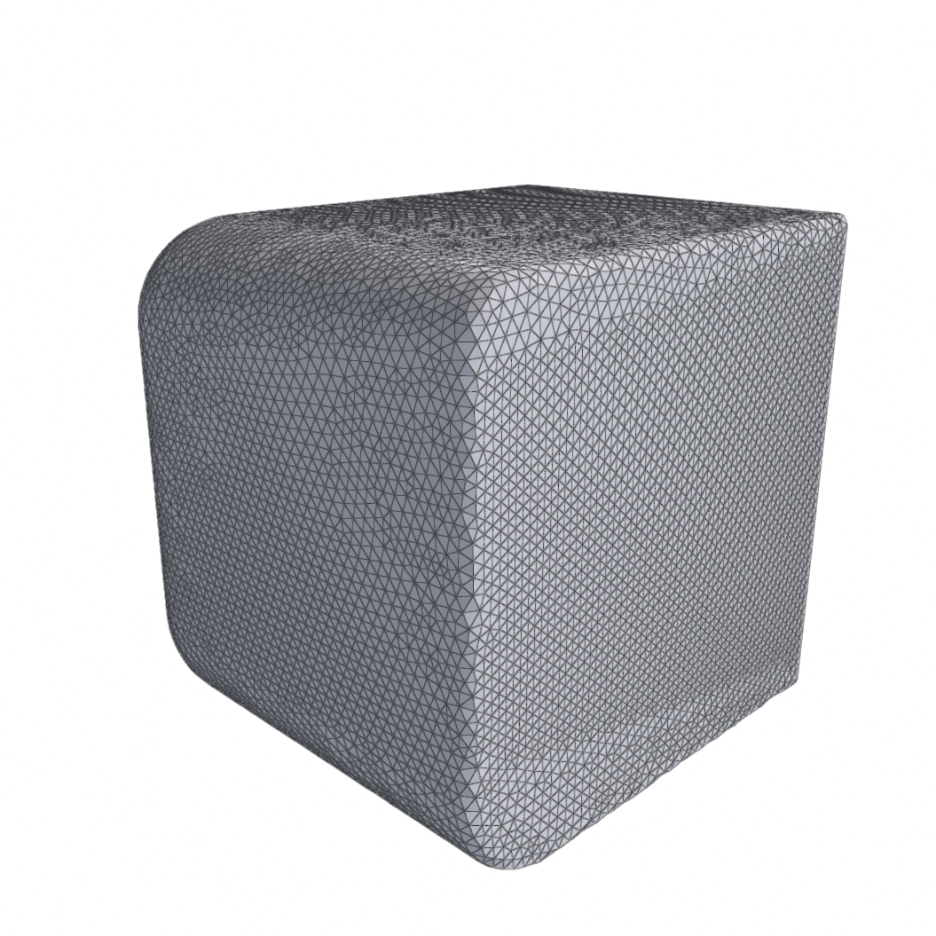
Apply SRT Transformation
| Method | What it does |
|---|---|
| SRT Transform | Apply a scale, then a rotation, then a translation to the mesh. The output mesh has the transform baked into its verts. |
Exports
| Modifier | Method | What it does |
|---|---|---|
| Export Collision Model (Export Mochi Model) | Mesh+SDF | Bake a grid SDF from the input surface and export the mesh plus SDF as a .mochi.h5. |
| Export Mesh File | Mesh File | Export the input mesh to a .glb or .obj in a chosen material color. |
Export Collision Model is what produces a .mochi.h5 collision model. Its
parameters govern the SDF bake. The stage's output buffer is the surface
reconstructed from the SDF.
Export Mesh File picks its format from the extension given in the filepath.
.obj and .glb are supported, anything else is exported as GLB by appending
.glb to the provided path. The Material Color is written into the glTF
baseColorFactor, so what you see matches what it writes. OBJ stores no
materials, so the color is ignored there.
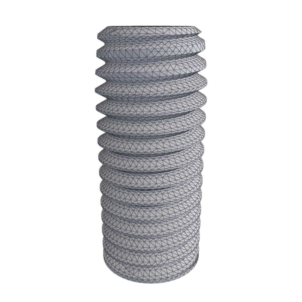
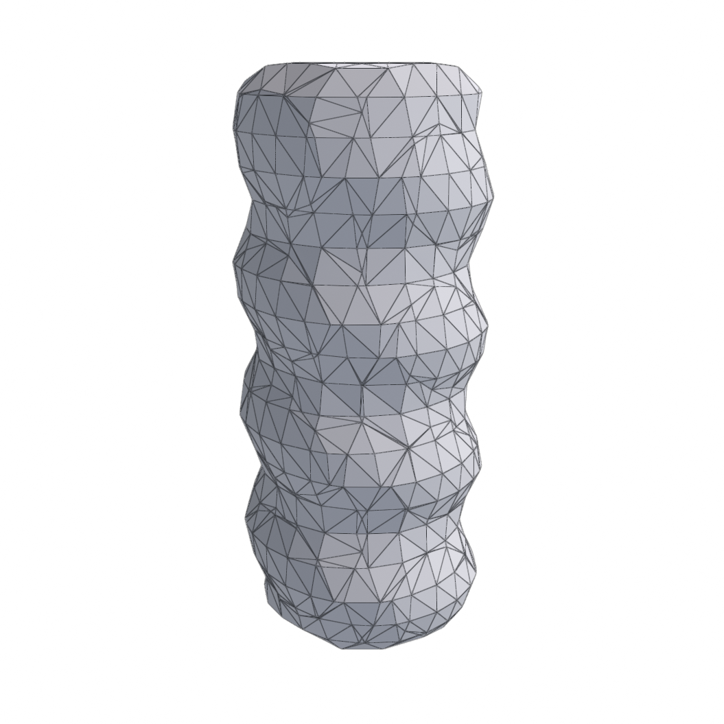
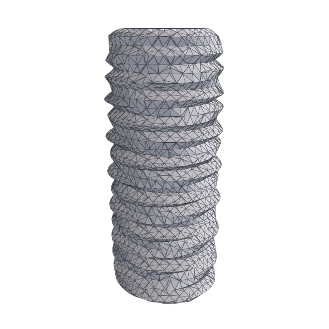
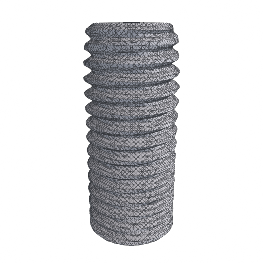
We have plans to update the mesh exporter to support texture mapping from one model to another that will manifest in a future version.
See Also
- User Interface — the viewport camera, the Asset Browser, and the Log Console.
- Importing — the URDF importer, which produces the collision models you refine here.
- Bot Editor Guide — where a refined collision model gets bound to a link.
- Prefab Editor Guide — where a collision model gets bound to an actor.
- SuperDex CAD Exporter — plugins for SolidWorks and Siemens NX for exporting robots and high-quality, Studio-compatible meshes