SuperDex CAD Exporter Tutorial: SolidWorks
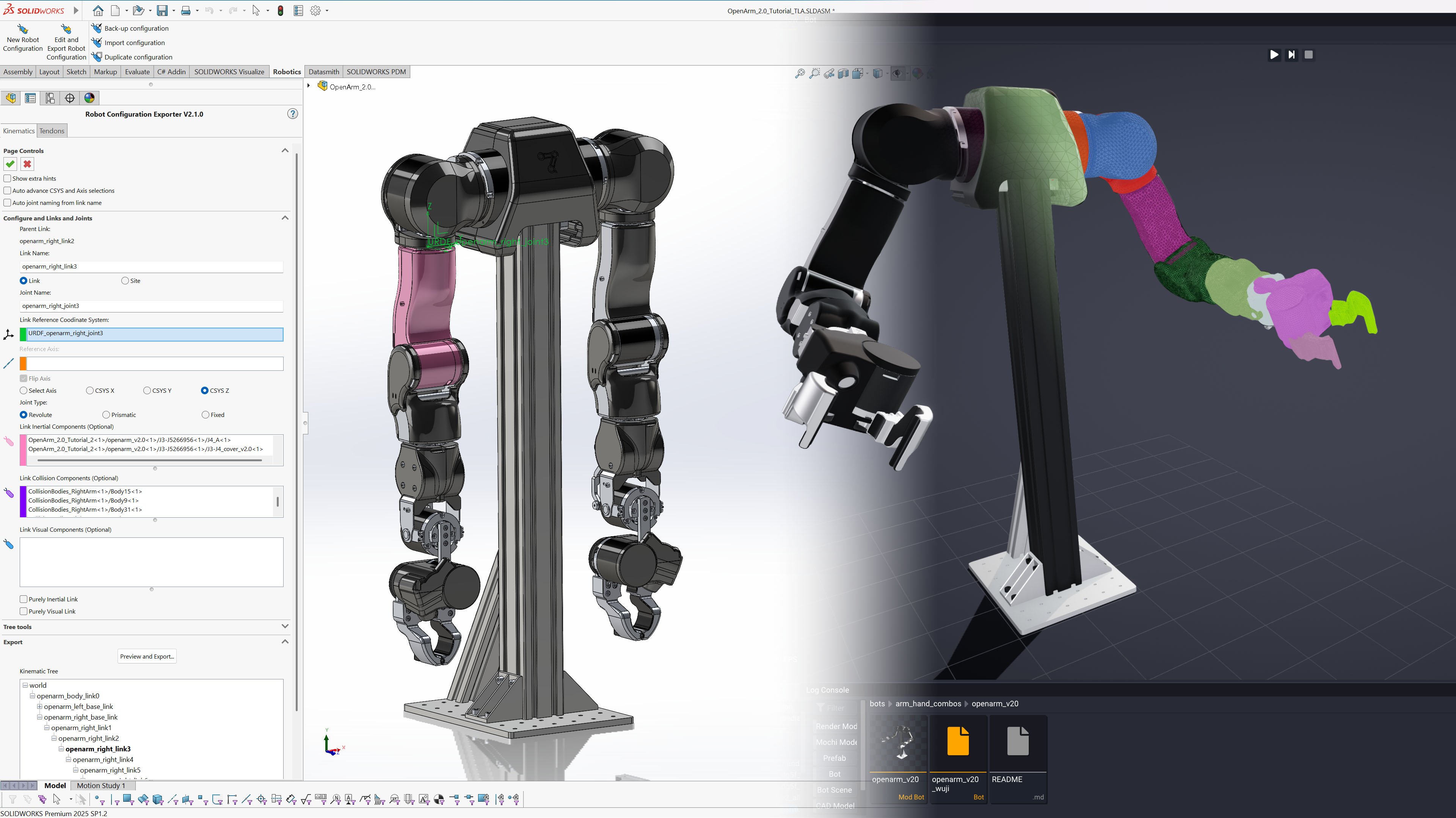
Assembly Preparation
The SolidWorks exporter currently only supports assemblies.
Before we begin, the following must exist in your part or assembly:
- Each link must be represented as a combination of components in the assembly. This means that parts with multiple bodies that span multiple links must be split into multiple parts.
- Coordinate Systems for each link/joint's local transform/origin. These can be at any level of the assembly (i.e. nested in parts).
- If the joint axis is not coincident with any of the principal axes (±X, ±Y, ±Z) of the CSYS, then an Axis must be defined. This can also be at any level of the assembly or part. The Axis' label is considered the "arrow" signifying the pointing direction of the axis.
- If any link requires precise mass and inertial properties, then that link's parts/components must have a material on them.
Importing an Existing Robot (Optional)
The exporter supports multiple ways importing kinematic definitions of an existing robot:
- You can import a URDF, using Tools menu (not the tab) → Robotics → Import URDF. Coordinate Systems for all joints will be generated with the URDF's origin defined using the selected Coordinate System. Axes will be generated on joint axes that do not lie any CSYS axis. The tool will create a Robot Configuration feature prepopulated with link/joint names, joint limits, joint types, CSYS, axes.
- You can import an existing Robot Configuration, saved from either NX or Solidworks (via the Back-up configuration button), and imported using the Import configuration button. The imported configuration may include valid selections (CSYS, bodies/components, axes) for links if the assembly or part is derived or copied from the original. All other properties, such as link names and joint types, should be imported.
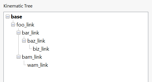
- You can create a New Robot Configuration, and use the Import Tree (.txt) button under Tree Tools.
The format is:
base
  foo_link  foo_joint  [fixed]
    bar_link  bar_joint  [fixed]
      baz_link  baz_joint  [revolute]
        biz_link biz_joint  [revolute]
    bam_link  bam_joint  [revolute]
      wam_link  wam_joint  [fixed]
Which results in:
Joint names and joint types can be omitted, where joints are revolute by default, which is then even shorter:
base
  foo_link
    bar_link
Setting up a Robot Configuration
Let's create a robot arm from an assembly in SolidWorks.
-
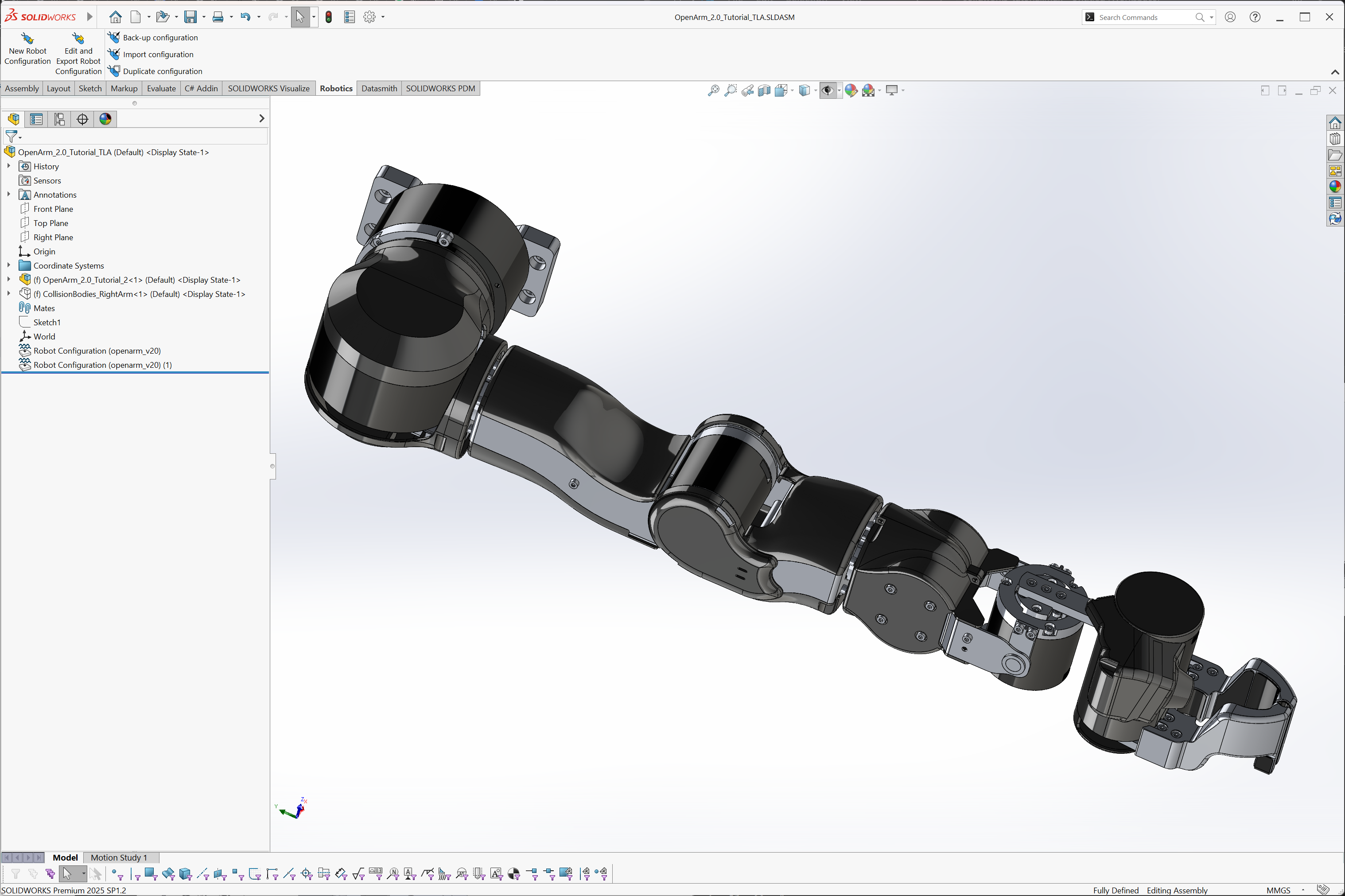
The arm we are exporting is the OpenArm V2.0. The assembly shown was imported from the downloadable STEP assembly and visual properties were applied to loosely match the real arm's colors.
-
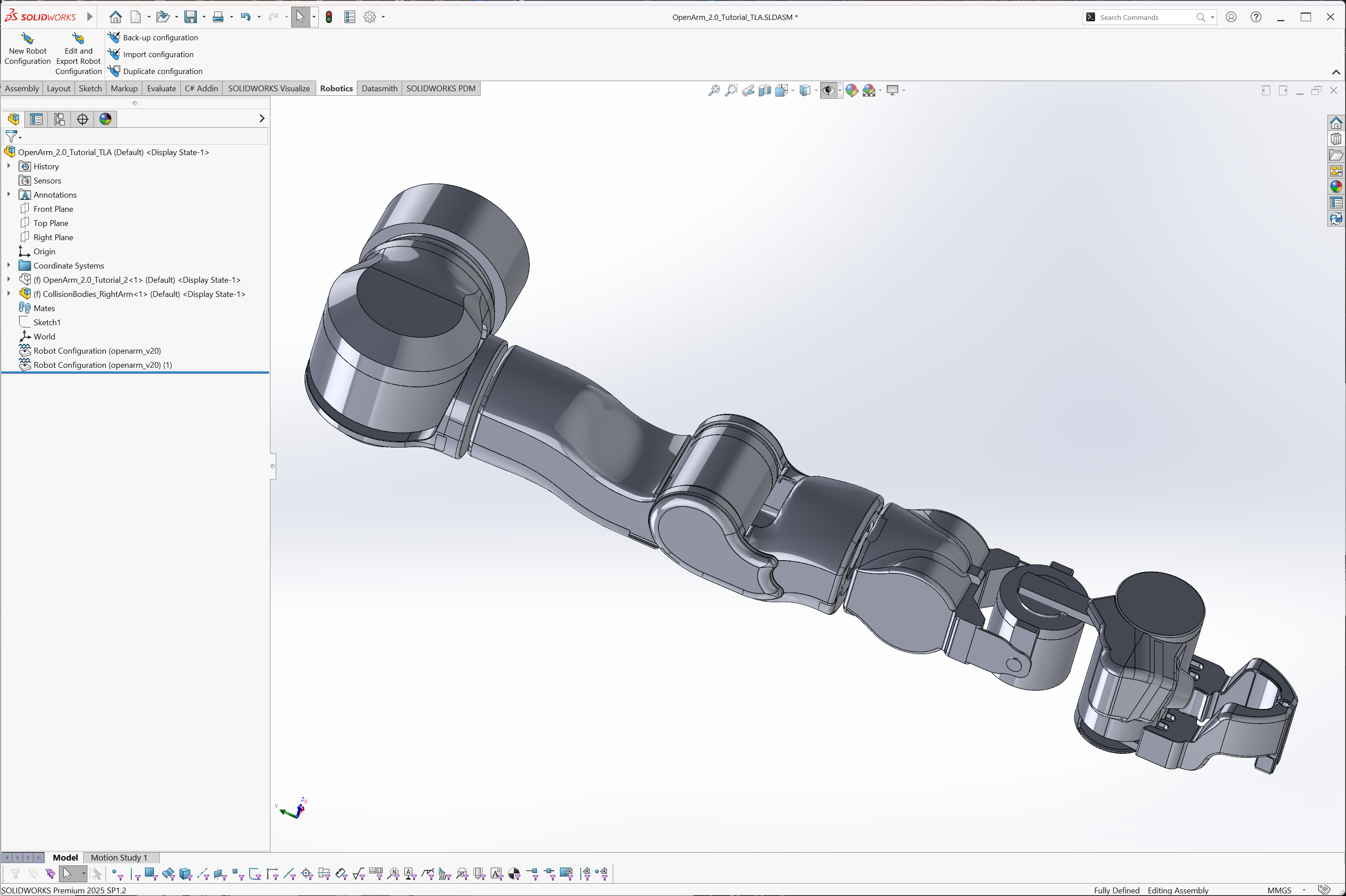
We've also added simplified geometry, modified from the original files, to serve as collision bodies. These bodies have features and details removed aiming to preserve fidelity and reducing meshing complexity.
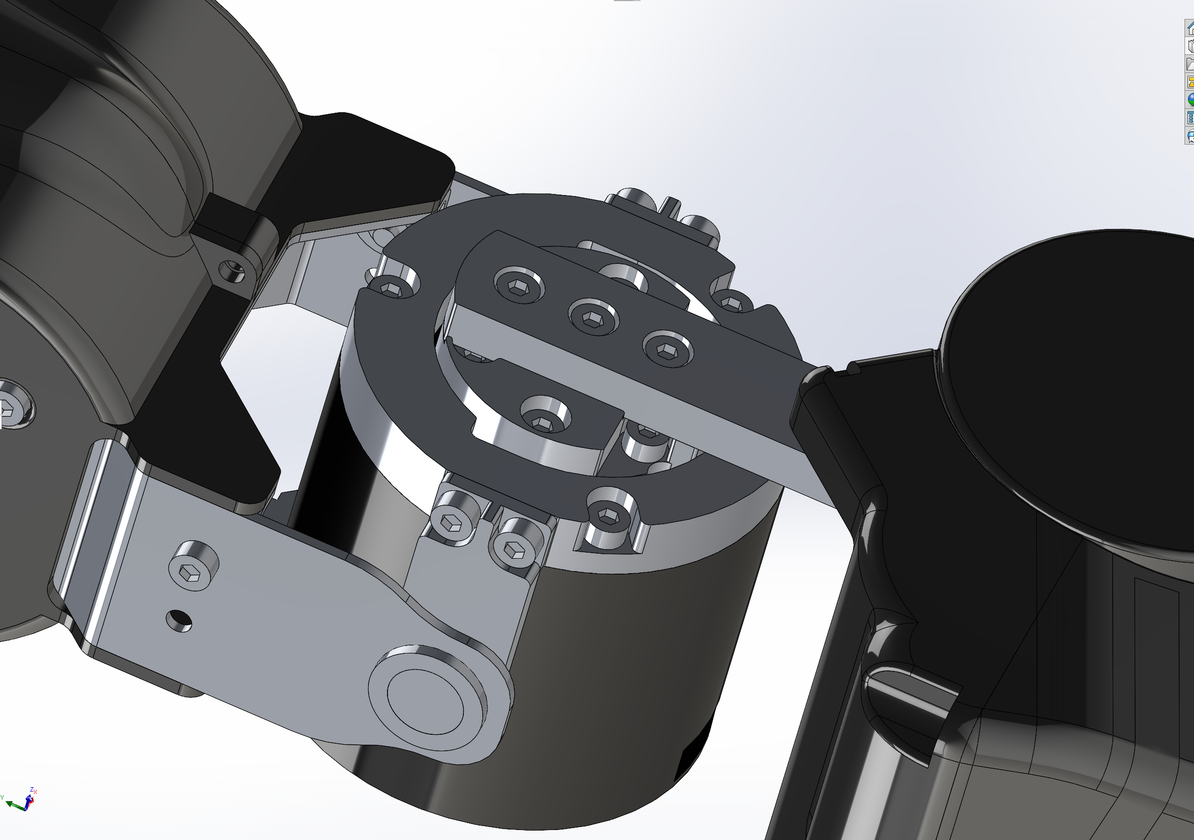
Visual/Inertial details 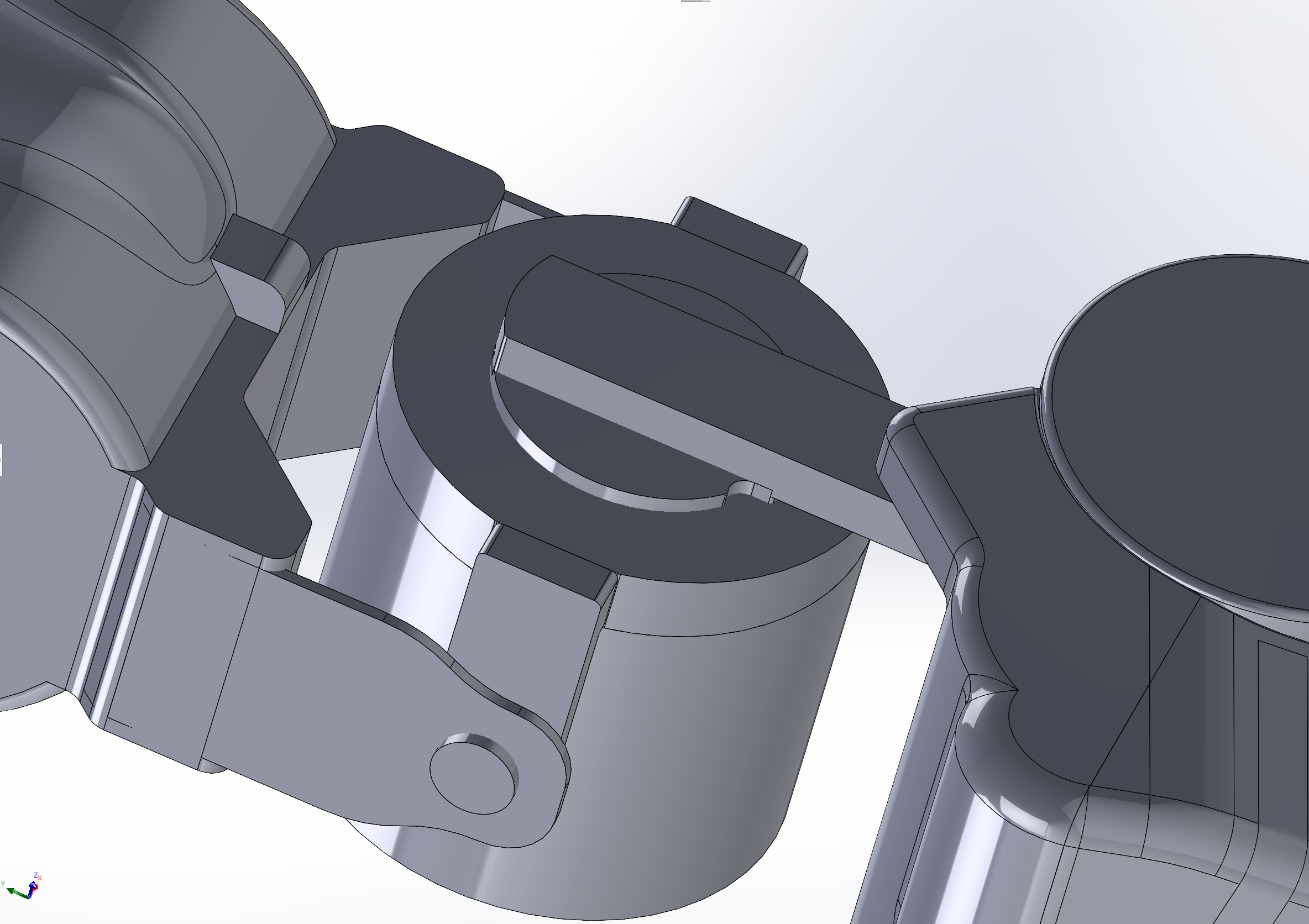
Simplified collision geometry -
The arm has been adorned with Coordinate Systems representing the joint/link origins at the part level as features. Alternatively, Coordinate Systems can be defined at the top level assembly, subassembly, or imported from a URDF (see above).
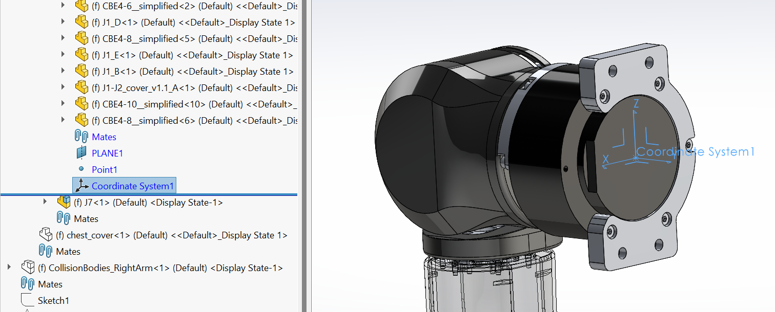
-
Let's start by creating a new Robot Configuration. From the Robotics tab, select New Robot Configuration.
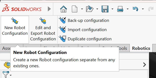
-
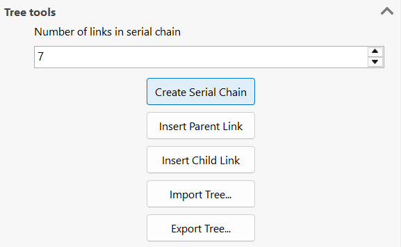
In the Robot Configuration dialog that comes up, expand the Tree Tools group.
-
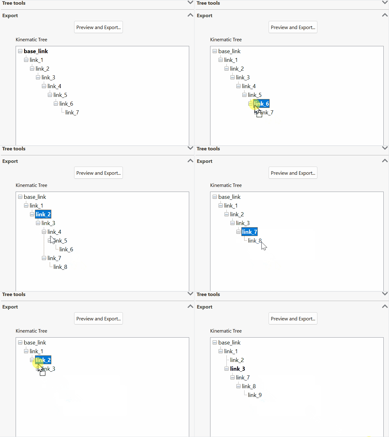
Since we know the arm has 7 degrees of freedom and we want 1 extra fixed joint to define the gripper's attachment point. With the base_link selected, we put in 7 for Number of links in serial chain and hit Create Serial Chain.
-
The Kinematic Tree allows for modifications of the tree via drag-n-drop, and right-clicking on the nodes. For instance, we'll add some child links to represent the end effector links.
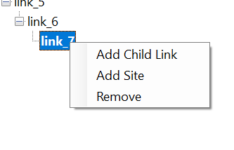
Context menu for Links 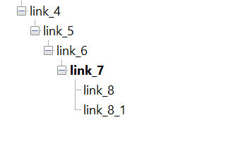
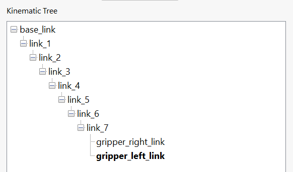
link_8 and link_8_1 represent the left and right grippers -
Links can be renamed by editing the Link Name field at the top of the dialog. You can also use Automatic Joint naming under the Options flyout for the exporter to name the joints automatically by either prefixing with
joint_or replacing the wordlinkwithjoint.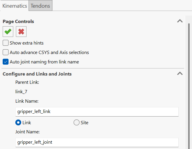
-
For each link we will do the following:
Order of operationsIt is generally easier to perform the following on each selection type (select all Coordinate Systems, then all Axes, then all Inertial Bodies, then all Visual Bodies, etc.) for all links and going through all links again and again, rather than going link-by-link and selecting all items for each link.
-
Select the Link/Joint Coordinate System for the link/joint's local transform/origin. For links other than the base link, set the Joint Type as well.
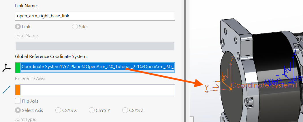
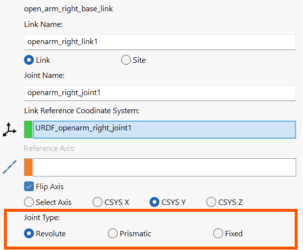
-
If the axis is coincident with one of the Coordinate System's axes, select that axis (CSYS X, CSYS Y, CSYS Z). If the axis is opposite, tick Flip Axis. If the axis is not coincident with any of the CSYS axis, then select an Axis in Joint Axis.
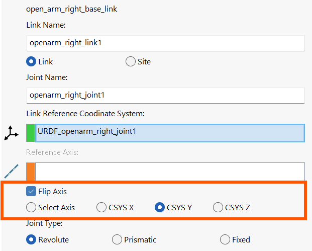
Usually choosing one of the Coordinate System's axes the most convenient option 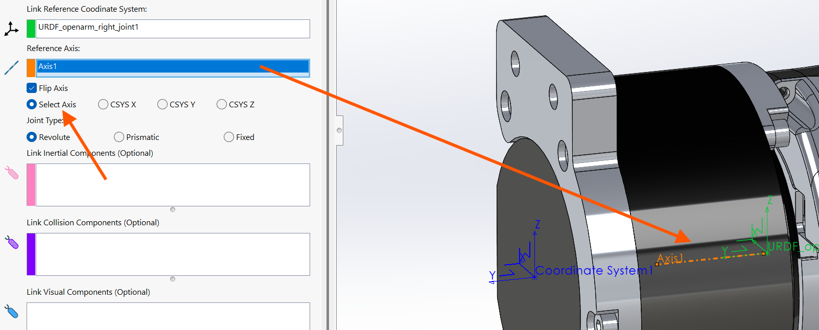
Use 'Select Axis' to select an Axis instead -
For the Inertial Bodies, we can select the component we want (which shown here is a subassembly) from the feature tree. This way, we have the most accurate inertial properties since all components under the subassembly are included.
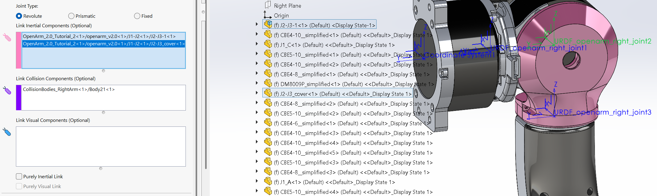
Either only Inertial Bodies or Visual Bodies are the bare minimum for mesh export, please consult the Link Export Guide Table for how visual and collision meshes are determined.
Rule of thumb for selecting Link bodies- Inertial Bodies have the highest fidelity and capture the true mass of the assembly
- Visual Bodies should capture visible external geometry.
- Collision Bodies should use simplified geometry where possible. Otherwise, collision geometry can be generated from Visual Bodies.
-
(Optional) For our Visual Bodies, however, we want only parts that can be seen visually, so only the visible parts are rendered in our high-fidelity renderers, saving precious rendering time.
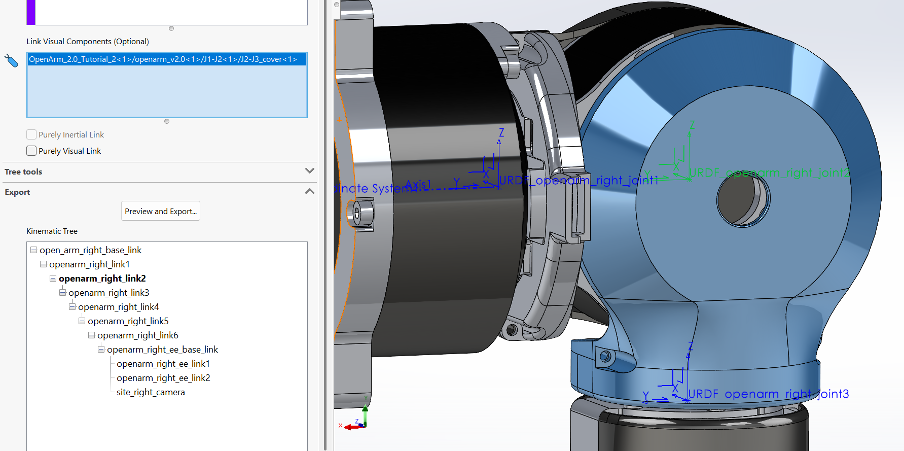
For visual bodies, we only select the visible components. Notice that the internal components are left unselected. -
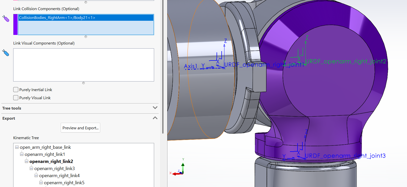
(Optional) We can also select Collision Bodies that have the simple geometry we have prepared earlier.
-
-
Once we're done we can hit Preview & Export… to continue.
At this point we can also hit ✓ at the top to take a breather, or save changes to the assembly
-
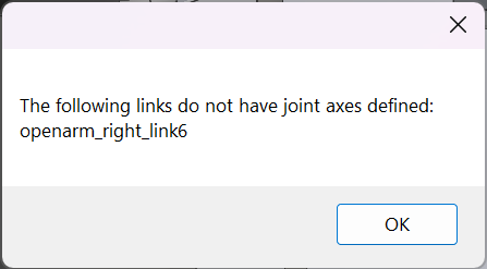
However, we forgot to populate link_6 with a joint axis, and we hit a validation error we need to fix before we can continue.
-
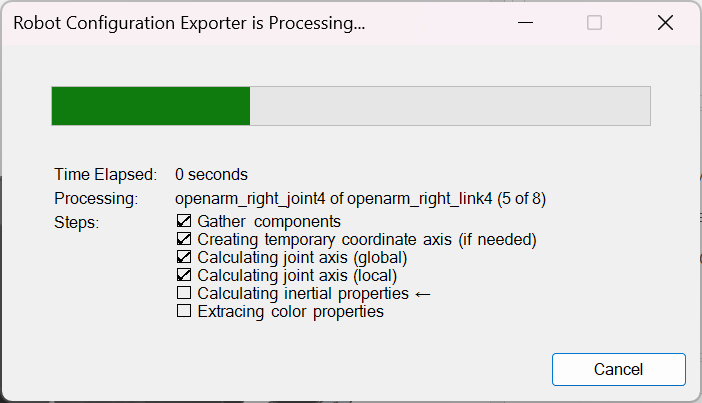
A progress bar appears briefly while the exporter creates temporary top-level CSYS, calculate inertial properties, and axis transforms. Then we're presented with the exporter form.
Exporting a Robot Configuration
-
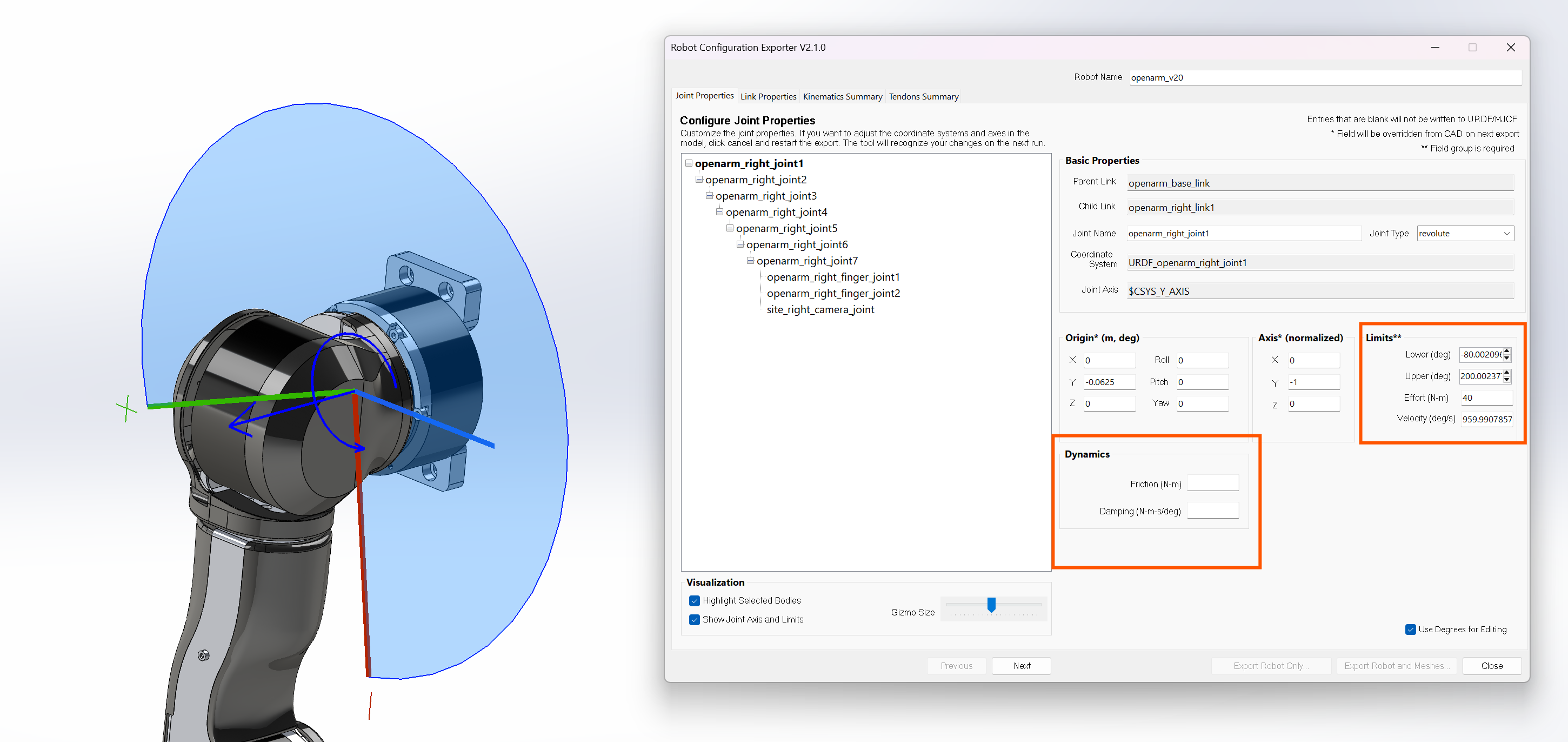
From here, optionally, additional Joint Properties can be set for each joint such as limits and joint dynamics. For some users, this is left alone and a post-export script takes care of updating the limits from a joint-name-based look up. We can also name our robot, by default, it's the same as the assembly.
By default, joint axes and limits are drawn as lines and arcs in the viewport. You can customize these in the Visualization panel.
-
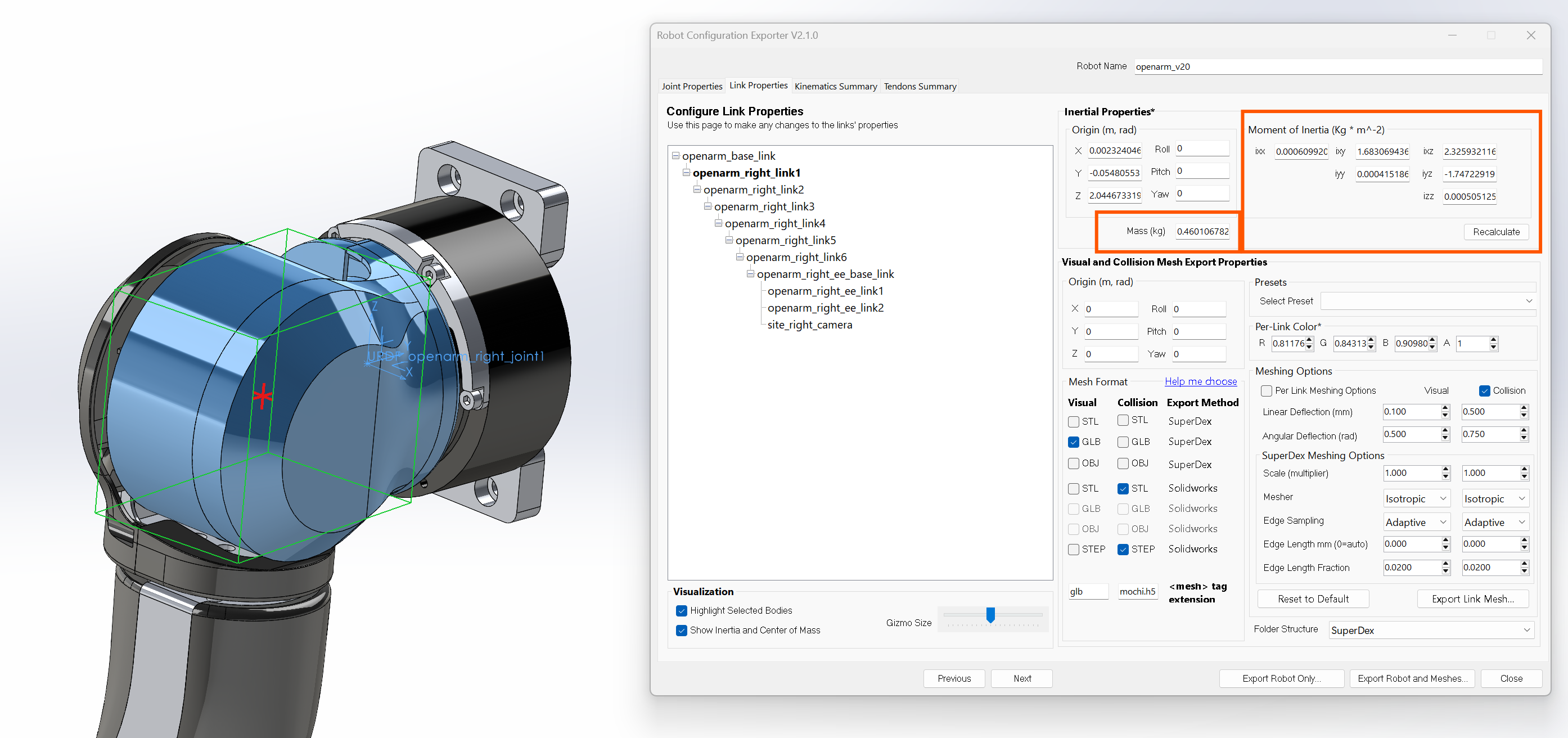
After we hit Next (bottom-center button, or the Link Properties tab above), we're presented with the link's Inertial Properties and numerous meshing options.
-
At this point, we can confirm that the Inertial Properties of the link are what we expect, and then we can figure out our meshing options.
-
By default equivalent inertial boxes and center of mass are drawn as lines in the viewport. If lines are occluded, you can turn off Highlight Selected Bodies.
-
You can consult the Mesh Export Guide table for guidance on what to choose, but there are also Presets that are good starting points. You can also save your own Presets and share them with your colleagues (so your entire team has the same settings).
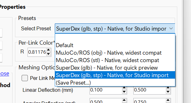
Presets are saved to and loaded from C:/Users/<username>/sw2urdf/presets -
For Visual Meshes, using the GLB SuperDex option is best for maintaining visual fidelity.
-
SuperDex options for meshing require an intermediate STEP file to be exported, so they can be slow for large assemblies, but offer higher quality face tesselation.
-
Per link meshing options are useful for controlling meshing fidelity at the link level. For instance, if you want fingertip meshes to have higher fidelity for contact simulation.
-
STEP format isn't really a mesh, but is useful for software that can tessellate STEP files to triangular or tetrahedral meshes, including SuperDex Studio.
For SuperDex StudioWe highly recommend the SuperDex (glb, stl, stp) - Studio import preset to process the STEP geometry in SuperDex Studio.
-
From here you can also hit Export Link Mesh… if you ever come back and want to export a single link's mesh (say, after updating some features) rather than the entire package.
-
The Folder Structure dropdown lets you configure the output mesh folders:
- Legacy -
meshesandmeshes/collisionfolders, visual mesh files have no suffix, collision mesh files have_collisionsuffix. - ROS -
meshesandmeshes/collision,_visualsuffix,_collisionsuffix - MuJoCo - single
meshesfolder,_visualsuffix,_collisionsuffix - SuperDex -
renderandcollision,_rendersuffix,_collisionsuffix
- Legacy -
-
-
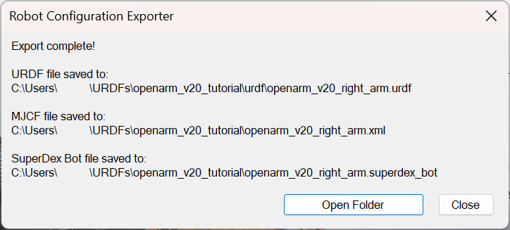
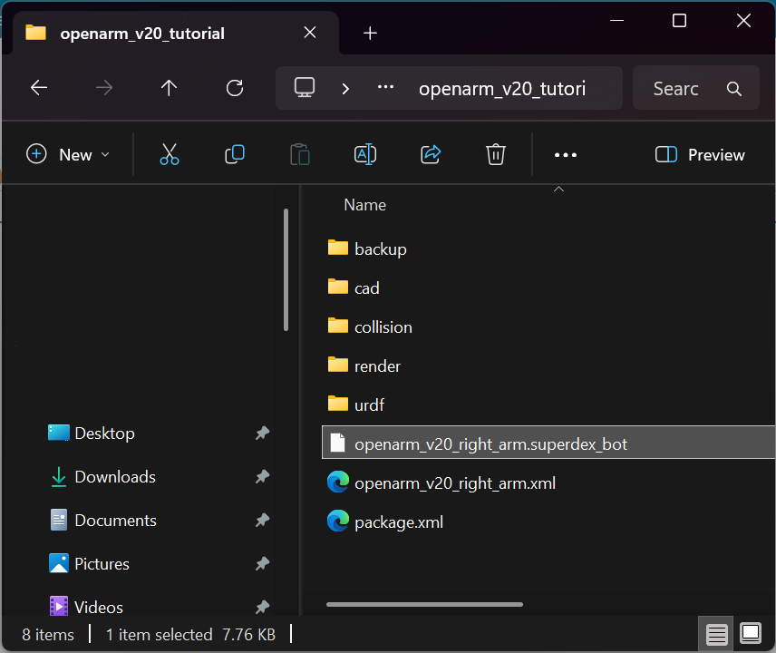
After we've made our choices, we can hit Export Robot and Meshes… and choose where to save our robot package. This may take a while, depending on what the meshing options are. The resulting package contains:
- a .superdex_bot file in the root directory
- a .urdf under
/urdf - an mjcf .xml file in the root directory
- visual and collision meshes deposited in their corresponding folders.
- backups of the Robot Configuration and meshing options in /backup (paired .xml and .json files)
- and a dummy package.xml file (for strict URDF importers)
-
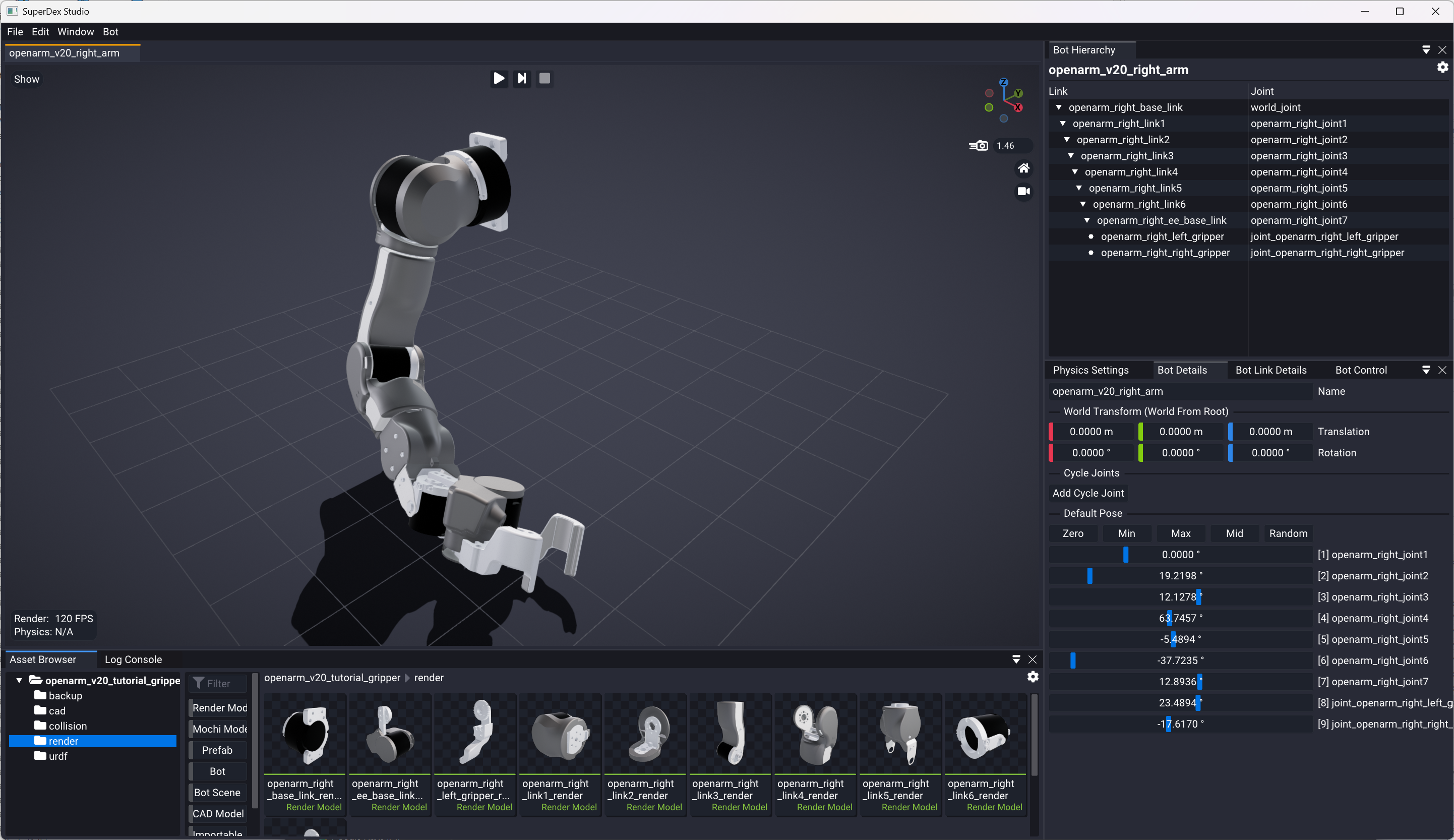
All done! From here, you can copy the entire folder into your current SuperDex Studio's workspace for further processing.
See also
- Model Editor Guide — post-export processing in SuperDex Studio
- URDF Import — importing URDFs into NX and SolidWorks